900 Series Temperature Chamber INSTRUCTION MANUAL C-155 PN 122648 REVISION D 1/2011
Notice Users of this equipment must comply with operating procedures and training of operation personnel as required by the Occupational Safety and Health Act (OSHA) of 1970, Section 6 and relevant safety standards, as well as other safety rules and regulations of state and local governments. Refer to the relevant safety standards in OSHA and National Fire Protection Association (NFPA), section 86 of 1990.
i
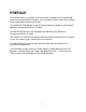
PREFACE This manual contains instructions for all accessories available on the Despatch 900 Series Environmental Bench Chamber. You may want to mark the parts of the manual that are applicable to your particular oven. The INTRODUCTION provides a brief overview of options available for the Despatch 900 Series Environmental Bench Chamber. The INSTRUCTIONS cover the installation and operation of the 900 Series Environmental Bench Chamber.
Revision B: Updated schematic diagrams Revision C: Update Despatch Product Warranty Revision D: Update Controller information, cover, warranty iii
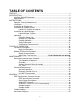
TABLE OF CONTENTS PREFACE ........................................................................................................................ii INTRODUCTION ............................................................................................................. 3 230 Volt, 50/60 HZ Operation ............................................................................... 3 Specifications .......................................................................................................
2
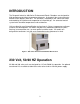
INTRODUCTION The Despatch Industries 900 Series Environmental Bench Chambers are designed for high performance and close temperature tolerance. A closed air flow system transfers heat to or from objects under test. The chamber is heated by a low- inertia coil heater and cooled by the injection and evaporation of a liquefied gas. An advanced control system holds chamber temperature to close tolerance.
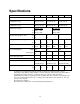
Specifications Model 924 Test Volume in cubic feet (liters) 0.4 ft (11.3) 0.78 ft (22.1) 0.78 ft (50.4) Workspace Dimensions (width x depth x height) inches (cm) 10 x 10 x 7 in 25 x 25 x 18 cm 14.5 x 11 x 8.5 in 37 x 28 x 22 cm 20 x 14 x 11 in 51 x 36 x 28 cm Exterior Dimensions (width x depth x height) inches (cm) 17.5 x 18.5 x 11 in 17.5 x 19 x 19.5 in 35 x 24.5 x 15.
INSTRUCTIONS Operator Training Requirements All users must be thoroughly trained under the supervision of experienced personnel. The operator must aware of the danger of: suffocation from nitrogen and carbon dioxide gases, frostbite from nitrogen or carbon dioxide as liquid or frozen gases, fire. User(s) must demonstrate an understanding of the equipment and its operation to assure knowledge of and practice of safe and proper operating procedures.
Installation 1. Remove all packing materials. 2. Inspect the oven for damage of any kind that could have occurred during shipment. 3. See whether the carton and plastic cover sheet inside carton are still in good condition. Look at all outside surfaces and corners of the oven for scratches and dents. Attention: NOTE: Always refer to the electrical Check the oven controls and schematic for exact instructions on your indicators for normal movement, bent shafts, cracks, equipment.
6. 7. 8. Install the power cord. The 920 series units are equipped with a 20 amp, 120 volt rated plug designed to be plugged into a Hubbell Model 5362, or equal, receptacle. This plug is required by the NEC and will provide necessary protection for this chamber installation.
Installation of Cooling Gas If the test chamber is to be cooled below chamber ambient temperature, it is necessary to provide a source of liquefied coolant gas. The type, quality, and handling of the gas is quite important as is the plumbing used to deliver the gas to the test chamber. Most test chamber operational problems are caused by improper gas use; thus, the installation procedures and precautions should be reviewed carefully before operating the chamber.
Installation of Carbon Dioxide Before purchasing or installing CO2 gas supplies, insure that the test chamber is the correct model to use CO2 (High - 70 Kg/cm2 or 1,000 PSI or Low - 21 Kg/cm2 or 300 PSI) and that the desired low temperature can be reached by use of this gas. The following special CO2 requirements must be met: The liquid CO2 should be furnished by a reputable source. The liquid CO2 cylinder must be a siphon-type. Syphon tank will have a red neck.
A filter installed in the line must be checked for cleanliness every 50 hours of operation, or more often if necessary. Clean the filter in trichloroethylene and dry thoroughly using filtered, moisture-free compressed air at low pressure. It is important that the CO2 solenoid valve assembly and the orifice be kept clean. Additional Precautions Never install CO2 supply pipe fittings or valves of a larger internal diameter than those used upstream [beginning at the supply cylinder(s)].
Pressure of Solid, Liquid and Saturated Vapor CO2 Temperature (F) Pressure (PSIA) Temperature (F) Pressure (PSIA) -140 3.19 -20 215.02 -130 5.39 -10 257.46 -120 8.85 0 305.76 -110 14.22 +10 360.4 -100 22.34 20 421.8 -90 34.05 30 490.6 -80 50.70 40 567.3 -70 74.90 50 652.7 -69.9 75.1 (triple point) 60 747.4 -60 94.75 70 852.5 -50 118.27 80 969.3 -40 145.87 87.8 1072.1 -30 177.
12
Liquid CO2 Cylinder Installation For extensive use at low temperatures, it is recommended that two or more liquid CO 2 cylinders be used in parallel. This will increase operating time between cylinder changes. Install the liquid CO 2 cylinder(s) as follows. 1. Turn off POWER switch and disconnect AC input power. 2. Position the cylinder in a safe and convenient location. 3. Secure the cylinder in an upright position with safety chains. 4.
b. Shut off the valve at the cylinder. c. Crack the hose fitting slightly, and allow the residual CO2 pressure in the hose to bleed off before disconnecting the hose. d. Connect hose to new cylinder. e. Open cylinder valve. f. "Crack" the fitting at the bulkhead to bleed off gas and moisture. g. Turn chamber on. Installation of Liquid Nitrogen Some models of test chambers use pressurized liquid nitrogen (LN 2) so that lower test temperatures may be reached.
gaseous constituents of the air which liquefy above -196 C (-320 F), including oxygen. Therefore, supply lines, clothes and equipment which are subject to this temperature can absorb or liquefy oxygen, which will cause a severe fire if ignited and which can become explosive when in contact with grease. LN2 should not be left in sealed containers or hoses. When the LN 2 turns to nitrogen gas, it will build up very high pressure.
Liquid Nitrogen Cylinder The liquid nitrogen cylinder is connected to the test chamber by the hose assembly. To prevent ice crystals in the coolant line from entering the test chamber, an ice filter (optional) may be connected between the LN2 cylinder and the test chamber. Slide NOTE: the insulation over the fittings after connecting to the bulkhead fitting and the coolant source.
The ice filter eliminates ice crystals and prevents them from freezing up valves or intruding into the test chamber. The ice filter should be cleaned periodically by a reverse purge using dry nitrogen. Install the LN2 cylinder as follows. 1. Turn off POWER switch and disconnect AC power. 2. Position the cylinder in a safe and convenient location. 3. Connect the cylinder to the test chamber as indicated.
Operating WARNING: WARNING:Do not use oven in Users and operators of this oven must comply with wet, corrosive or explosive operating procedures and training of operating personnel as required by the Occupational Safety and atmospheres unless this oven is specifically designed for a Health Act (OSHA) of 1970, Section 5 and relevant special atmosphere. safety standards, and other safety rules and regulations of state and local governments.
Heating Only Operation For heating only applications, when the Avoid WARNING: adapters that will either unground the chamber is heated only above chamber chamber or will permit connection to the ambient, cooling gas supplies and wrong power source. Check the current plumbing are not needed. Operation of rating of the circuit. the chamber then requires setting the temperature control and over-temperature safety set-points.
Cooling Operation Cooling operations with the chamber are essentially the same as those for heating operations. Refer to the manufacturers controller instructions to familiarize yourself with the operation of this control. 1. Attach the test fixture or tray to the chamber. 2. Insure that the POWER switch is off. 3. Connect LN2 supply. 4. Turn on supply valve. 5. Plug in the chamber power cord to the correct line power.
To avoid moisture collection in the insulation after sustained operation at low temperatures, the test chamber should be operated for at least one hour at 205 C (400 F) to evaporate the moisture. Do not exceed this temperature with the cryogenic models which are insulated with high-temperature-resistant polyurethane (isocyanate) foamed-in-place resin. This insulation will be damaged if temperatures in excess of 205 C (400 F) are sustained.
4. Find the minutes needed to reach the desired temperature in the middle columns under MINUTES NEEDED TO REACH TEMPERATURE. Column AIR lists the time required for the air in the chamber to reach the selected temperature. The AIR + WALLS column lists the associated total time required for the air and walls to reach the selected temperature.
Performance Characteristics, Model 925 Temp. Set Points Minutes Needed to Reach Temp.
Performance Characteristics, Model 934 Temp. Set Points Minutes Needed to Reach Temp.
Performance Characteristics, Model 936 Temp. Set Points Minutes Needed to Reach Temp.
THEORY OF OPERATION This section contains a functional as well as a detailed circuit description of the temperature control circuits in all models of these chambers. Functional Description The Despatch 900 Series Environmental Bench Chamber uses a closed airflow system to transfer heat to or from objects under test. A low inertia electric coil heater is used for elevated temperatures in the chamber.
An over-temperature circuit protects the test chamber and test objects by removing power to heaters when the test chamber exceeds the maximum rating of the chamber (274 C). An adjustable high limit allows the maximum operating temperature to be selected or varied for each test. This dial type unit will interrupt the power to the heater if the chamber temperature exceeds the high limit setting.
High Limit Controller This chamber is equipped with a non-indicating high limit controller. Anytime the chamber temperature exceeds the limit set point, the control will trip, and conditioning will stop. Power will not be restored until the chamber temperature is within tolerance. Refer to the enclosed electrical schematic and the instrument instruction manual. To reset the high limit controller after tripping, allow the chamber to cool below the high limit set point.
Watlow EZ-Zone PM Controller The process value appears in the upper display and the set point is in the lower display. Keys and Displays Upper Display Description In the Home Page, displays the process value, otherwise displays the value of the parameter in the lower display. Temperature Units Indicates whether the temperature is displayed in Fahrenheit or Celsius. Percent Units Lights when the controller is displaying values as a percentage or when the open-loop set point is displayed.
Digital Communication Digital communication is available in the following formats: RS-232 Modbus® RTU RS-485 Modbus® RTU RS-232 is a common, unbalanced communication configuration. It is the type of communication supported by the typical COM1 and COM2 hardware of a standard PC. There are three main wires (negative transmit, negative receive, common). Some devices use other handshaking protocol wires (RTS, CTS, etc.), but Watlow controls do not. RS-485 is a balanced communication configuration.
31
MAINTENANCE DO NOT service this equipment without first disconnecting the electrical power to this unit. Disconnect main power switch or power cord. There are live circuits and connections even with power switch off. Repair of electrical systems should be performed by qualified mechanics only. Refer to the enclosed wiring and piping schematics with bills of materials for description and function of components. Keep equipment clean. Gradual dirt accumulation impedes air flow.
Check safety controls. This should be done as indicated. Make these tests carefully and do them regularly. The safety of personnel as well as the equipment may depend upon the proper operation of any one of these controls at any time. Temperature Controllers (weekly) Observe that the heater or cooling indicator lights (LEDs 1 or 2) flash every 1 to 2 seconds when the controls are operating at set point.
Preventative Maintenance Schedule Insure trouble-free service by performing preventive maintenance when appropriate. Should service be required, specific procedures are described to locate and repair malfunctions. Item Description Reading Months of Operation 1 3 6 1. Inspect door seals checking for proper seating, damage or tears. Adjust and/or replace as necessary. X 2. Inspect the door operation. Should open and close easily. X 3. Inspect recirculation fan.
Test Equipment Required The following equipment is needed to perform maintenance and calibration operations on temperature test chambers. Temperature calibrator (minimum adjustment 0.1 C or less). Multitester, 100k ohms/volt, or VOM. Chamber WARNING: WARNING:Always disconnect the AC power to the test chamber before performing preventive maintenance. The temperature test chamber should be Maintenance should be performed by inspected for conditions that might damage qualified personnel only.
Coolant Solenoid Orifice Assembly The coolant solenoid orifice assembly should be cleaned only when necessary. Frequent cleaning should not be required if contaminant-free CO2 is always used. Clean the coolant orifice as follows. 1. Disconnect AC power. 2. Disconnect coolant hose. 3. Remove vent screen from control unit compartment. 4. Open heater compartment. 5. Remove coolant solenoid assembly from control unit compartment. 6. Remove orifice tube from solenoid assembly. 7.
CO2 Filter The CO2 filter should be cleaned every 30 days or 240 hours of operation, whichever occurs first. See Figure 2 in this manual. Clean the CO2 filter as follows. 1. To remove the filter, unscrew the hollow Allen head screw from the test chamber bulkhead fitting and slide the filter out from the fitting. 2. Wash filter in trichloroethylene. 3. Dry filter thoroughly with filtered, dry, compressed air at low pressure. 4. Reinstall filter in CO2 bulkhead fitting.
Corrective Maintenance The purpose of corrective maintenance is to locate test chamber malfunctions and to apply proper repair procedures. The following procedure is used in troubleshooting the test chamber. 1. Insure that all switches are in the proper position. 2. Check first for blown fuses and proper AC power connection. 3. Check coolant lines for proper plumbing. Check that all line valves are open. Make sure that the coolant lines are not clogged. 4.
4. Remove two Phillips-head screws at the back of the heater assembly. 5. Remove the two wires connected to the heater coil. 6. Carefully remove heater from chamber. 7. To replace heater assembly, perform the removal procedure in reverse order.
Service Procedures Main Blower Motor Remove the main blower motor as follows. 1. Disconnect AC power. 2. Remove screws holding plenum plate. 3. Carefully allow plenum plate to drop downward. ATTENTION: CAUTION: Do not damage thermocouples or disturb placement. 4. Loosen Allen set screw holding blower motor fan blade or blower wheel to motor shaft. 5. Remove fan blade or blower wheel. In some cases, a gear puller will be needed for removal of the fan from the motor shaft. 6.
Electronic Control Chassis Remove the electronic control chassis as follows. 1. Disconnect AC power. 2. Remove vent screen from motor compartment. 3. Remove holding screw located above rear of Watlow 982 control within motor compartment. (On Models 934, 924, 936, and 926.) 4. Remove two holding screws on rear of chamber near the serial interface connector. 5.
HI-LIMIT Thermoswitch Adjust and test the factory calibrated HI-LIMIT thermoswitch as follows. 1. The thermoswitch was factory set and tested at the chamber maximum rated temperature within normal tolerance. 2. If necessary to reset the thermoswitch. It is accessible by removing the snap in closure button in the rear cover panel. 3. A screwdriver can be inserted through the hole to find the end of the slotted adjusting screw. 4. Turn screw clockwise to reduce temperature.
APPENDIX IEEE 488 Interface Converter Set-up Three DIP switches internal to the interface converter set the configuration of the interface. Selectable functions are read ONLY at power-on and should only be set prior to applying power to the interface. The following lists the Despatch factory recommended conditions.
The interface converter may also be configured as an IEEE peripheral. As an IEEE peripheral, the interface converter allows an IEEE controller to communicate with an RS-232 device (e.g., Watlow control). The peripheral mode of operation is described in detail in Section 4 of the Black Box manual. Note in this mode the address selected is for the IEEE488 converter itself. Each Watlow device must have its own converter with a unique address.
IEEE 488 Interface Converter The interface converter has the ability to output signal levels that are compatible with either RS-232 or RS-422. An internal DIP shorting plug determines which electrical specification is chosen. If the interface is to be connected to an IBM PC/XT/AT/PS2 or compatible, the RS-232 level should be selected. If it will be connected to a Macintosh 512K/Plus/SE/II, the RS-422 level should be used.
Serial Signal Descriptions The interface converter is equipped with a standard DB-25S connector on its rear panel and requires a standard DB-25P mating connector. The interface converter's connector is configured as DCE type equipment for RS-232 communications, which means the interface converter always transmits data on Pin 3 and receives data on Pin 2. The following lists and describes the RS-232 and RS-422 signals provided on the interface converter. The RS-422 pin outs are made similar to RS-530 DCE.
Pinout Descriptions Pin Out Description -RxD Receive Data Input - Pin 2 This pin accepts serial data sent by the RS-232 or RS-422 host. The serial data is expected with the word length, baud rate, stop bits and parity selected by the internal switches. The signal level is low true. -TxD Transmit Data Output - Pin 3 This pin transmits serial data to the RS-232 or RS-422 host. The serial data is sent with the word length, baud rate, stop bits and parity selected by the internal switches.
XON/XOFF Protocol Your Watlow control is selectable for use with one of two protocols: XON/XOFF, used when one master controls one Watlow. ANSI X3.28-1976 Sub 2.2 and A3, used to address multiple units in a single serial (RS-422/485) line. The XON/XOFF protocol on the Watlow uses a as a message terminator. The ANSI X3.28... uses various control characters (e.g., ETX, EOT).
Sample Program For the Black Box 488 to 232 converter. 10 20 30 40 50 60 70 80 90 100 110 120 130 140 150 160 170 180 190 200 210 220 230 240 250 260 270 280 290 300 310 320 330 340 350 360 370 380 390 400 410 420 Notes:HPIB interface is #7. Black Box is set for Address 10. Watlow control is set up for XON/XOFF. (Prot = on) mode.
Sample Output ? Response = aΩ9.0 Setpoint Changed to 5.5 ? Response = aΩaΩ5.5 Setpoint Changed to 125 ? Response = aΩaΩ125.0 Setpoint Changed to 2.5 ? Response =aΩaΩ2.
Troubleshooting TROUBLE PROBABLE CAUSE No controller display reading when power switch is on. Loose wiring. Faulty transformer (240V or 208V units only). Faulty readout. Power cord not plugged into outlet. Outlet not powered. Defective line fuse (F1). Defective POWER switch (S1). Defective power cord. Blowing line fuse when power switch is turned on. Defective (grounded or shorted) heater (HTR-1). Defective motor(s) (shorted). Defective solenoid valve (shorted) (1).
Schematic Diagrams See the Electrical schematics of the 924/934, 925/935 and 926/936 series that are provided with the equipment.
53
924 Series w/982 Control excerpt from drawing 136672A01 54
925 Series w/982 Control excerpt from drawing 136699B00 55
925 Series w/982 Control excerpt from drawing 136699B01 56
934 Series w/982 Control excerpt from drawing 140316A00 57
925 Series w/982 Control excerpt from drawing 140316A01 58
935 Series w/982 Control excerpt from drawing 140318A00 59
935 Series w/982 Control excerpt from drawing 140318A01 60
936 Series w/982 Control excerpt from drawing 140320B00 61
936 Series w/982 Control excerpt from drawing 140320B01 62