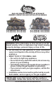
GAS LOG VENTED DECORATIVE APPLIANCE OWNER’S OPERATION AND INSTALLATION MANUAL Vtd-18N-PDG, Vtd-18P-PDG Vtd-24N-PDG, Vtd-24P-PDG Vtd-18N-BTB, Vtd-18P-BTB Vtd-24N-BTB, Vtd-24P-bTB WARNING: If the information in this manual is not followed exactly, a fire or explosion may result causing property damage, personal injury or loss of life. — Do not store or use gasoline or other flammable vapors and liquids in the vicinity of this or any other appliance.
TABLE OF CONTENTS Safety Information................................................ 2 Local Codes......................................................... 4 Product Identification............................................ 5 Unpacking............................................................ 5 Product Features.................................................. 5 Optional Remote Control Accessories.................. 5 Installation............................................................
Safety Information Continued WARNING: This product contains and/or generates chemicals known to the State of California to cause cancer or birth defects or other reproductive harm. WARNING: Keep flue open when operating unit. IMPORTANT: Read this owner’s manual carefully and completely before trying to assemble, operate or service this heater. Improper use of this heater can cause serious injury or death from burns, fire, explosion, electrical shock and carbon monoxide poisoning.
safety information Continued You must operate this heater with a fireplace doors or screen in place and fully closed. Unless provided by other means, screens shall have openings for introduction of combustion air. Keep the appliance area clear and free from combustible materials, gasoline and other flammable vapors and liquids. 1. This appliance is only for use with the type of gas indicated on the rating plate. This appliance is not convertible for use with other gases. 2.
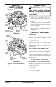
Product Identification Log Set Assembly Electronic Ignitor Control Knob Flame Adjustment Selector Knob Switch Hand-Held Remote Control Remote Receiver Chassis Assembly Unpacking CAUTION: Do not remove the data plates from the grate assembly. The data plates contain important warranty and safety information. 1. Remove log set assembly from carton. Note: Do not pick up assembly by logs. This could damage heater. Always handle assembly by grate. 2. Remove control cover floor media components. 3.
Installation WARNING: Make sure the selector switch is in the OFF position before installing heater. WARNING: Before installing in a solid fuel burning fireplace, the chimney flue and firebox must be cleaned of soot, creosote, ashes and loose paint by a qualified chimney cleaner. Creosote will ignite if highly heated. A dirty chimney flue may create and distribute soot within the house. Inspect chimney and firebox flue for damage. If damaged, repair flue and firebox before operating heater.
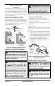
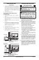
Installation Continued The minimum flue sizes shown in Figure 3, page 6, are based on a 6' chimney height using round pipe. Your minimum flue size will vary based on input rate and chimney height. Refer to the National Fuel Gas Code ANSI Z223.1/NFPA 54, Section 6.6 for details. Installing Damper Clamp Secure damper stop clamp to edge of damper as shown in Figure 4.
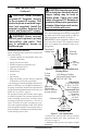
INSTALLATION Continued CAUTION: Never connect propane/LP fireplace directly to the propane/LP supply. This heater requires an external regulator (not supplied). Install the external regulator between the heater and propane/LP supply. WARNING: Never connect natural gas fireplace to private (non-utility) gas wells. This gas is commonly known as wellhead gas. Installation Items Needed Before installing heater, make sure you have the items listed below.
INSTALLATION Continued Check your building codes for any special requirements for locating equipment shutoff valve to fireplaces. Apply pipe joint sealant lightly to male NPT threads. This will prevent excess sealant from going into pipe. Excess sealant in pipe could result in clogged heater valves. WARNING: Use pipe joint sealant that is resistant to liquid petroleum (LP) gas. We recommend that you install a sediment trap in supply line as shown in Figure 7, page 8.
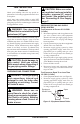
Installation Operating Heater Continued 3. Check all joints from gas meter to equipment shutoff valve for natural gas or propane/LP supply to equipment shutoff valve for propane/LP (see Figure 9 or 10). Apply noncorrosive leak detection fluid to all joints. Bubbles forming show a leak. 4. Correct all leaks at once. Pressure Testing Heater Gas Connections 1. Open equipment shutoff valve (see Figure 8, page 9). 2.
Operating Heater Continued lighting instructions NOTICE: During initial operation of new heater, burning logs will give off a paper-burning smell. Orange flame will also be present. Open damper or window to vent smell. This will only last a few hours. WARNING: Damper handle will be hot if appliance has been running. CAUTION: A mild gas flash within 10 seconds is normal during shutdown of this heater. Remain clear of the hearth area for the entire shutdown process to avoid possible injury.
Natural Figure 12 - Pilot (Remote Shown) TO TURN OFF GAS TO APPLIANCE Shutting Off Burner Only (pilot stays lit) You may shut off the burners and keep the pilot lit by doing one of the following: 1. Turn control knob clockwise to the PILOT position. 2. Use remote control manual OFF button. 3. Set selector switch in the OFF position. MANUAL LIGHTING PROCEDURE 1. Follow steps 1 through 6 under Lighting Instructions, page 16. 2. Depress control knob and light pilot with match. 3.
Inspecting Burners Check pilot flame pattern and burner flame patterns often. PILOT FLAME PATTERN Figure 14 shows a correct pilot flame pattern. Figure 15 shows an incorrect pilot flame pattern. The incorrect pilot flame is not touching the thermocouple. When the thermocouple cools, the heater will shut down.
Cleaning and Maintenance WARNING: Turn off heater and let cool before cleaning. CAUTION: You must keep control areas, burner and circulating air passageways of fireplace clean. Inspect these areas of fireplace before each use. Have fireplace and chimney inspected yearly by a qualified service person. Fireplace may need more frequent cleaning due to excessive lint from carpeting, bedding material, pet hair, etc. Only limited cleaning will be required under normal use of this appliance.
Troubleshooting WARNING: Turn off heater and let cool before servicing. Only a qualified service person should service and repair heater. CAUTION: Never use a wire, needle or similar object to clean ODS/pilot. This can damage ODS/pilot unit. Note: All troubleshooting items are listed in order of operation. OBSERVED PROBLEM POSSIBLE CAUSE REMEDY When ignitor button is pressed, 1. Ignitor electrode not connected 1. Reconnect ignitor cable there is no spark at ODS/pilot to ignitor cable 2.
troubleshooting Continued OBSERVED PROBLEM POSSIBLE CAUSE REMEDY ODS/pilot lights but flame goes 1. Control knob not fully pressed in 1. Press in control knob fully out when control knob is re- 2. Control knob not pressed in 2. After ODS/pilot lights, keep leased control knob pressed in 30 long enough seconds 3. Safety interlock system has 3. Wait one minute for safety interlock system to reset. Repeat been triggered ignition operation 4. Equipment shutoff valve not 4.
troubleshooting Continued OBSERVED PROBLEM POSSIBLE CAUSE Orange flame in burner during 1. Not enough air burner combustion 2. Gas regulator defective REMEDY 1. Check burner for dirt and debris. If found, clean burner (see Cleaning and Maintenance, page 14) 2. Replace gas regulator Slight smoke or odor during initial 1. Residues from manufacturing 1. Problem will stop after a few hours of operation operation processes and logs curing Heater produces a whistling noise 1. Turning control knob to HI 1.
troubleshooting Continued WARNING: If you smell gas • Shut off gas supply. • Do not try to light any appliance. • Do not touch any electrical switch; do not use any phone in your building. • Immediately call your gas supplier from a neighbor’s phone. Follow the gas supplier’s instructions. • If you cannot reach your gas supplier, call the fire department. IMPORTANT: Operating heater where impurities in air exist may create odors.
Service Hints When Gas Pressure Is Too Low • pilot will not stay lit • burners will have delayed ignition • heater will not produce specified heat • propane/LP gas supply may be low You may feel your gas pressure is too low. If so, contact your local propane/LP or natural gas supplier. Technical Service You may have further questions about installation, operation, or troubleshooting. If so, contact DESA’s Technical Service Department at 1-866-672-6040.
Illustrated Parts Breakdown Models vTD-18n-Pdg, vtd-18p-Pdg, vtd-18N-BTB AND vtd-18P-BTB Log Set, Ceramic Burner and Ramp Pan are Ordered as an Assembly 3 4 Air Shutter Installation Note: For Natural Gas: Fully Closed For Propane/LP Gas: Fully Open 6 4 5 7 4 2 20 8 9 10 20 18 11 1 13 19 10 12 16 15 4 17 14 Installed in BTB Models Only 20 www.desatech.
PARTS LIST 3 4 5 6 7 8 9 10 11 12 13 14 15 16 17 18 19 20 Grate Assembly Valve-Bracket Assembly Valve-Bracket Assembly Log Assembly Log Assembly Screw Screw Venturi/Shutter Assembly Gasket Orifice Orifice Valve NG Valve LP Valve Bracket Electronic Ignitor Control Knob Extension Control Knob Extension Fan Switch Remote Control Assembly Remote Receiver Bracket Flextube 3/16" Compression Nut/Sleeve Pilot Pilot Pilot Shield Screw 100563-01 103877-01 100639-01 GA6060 111288-02 112363-01 112364-01 Warning Pla
ILLUSTRATED PARTS BREAKDOWN Models vtd-24n-Pdg, vtd-24p-Pdg, vtd-24N-BTB AND vtd-24P-BTB Log Set, Ceramic Burner and Ramp Pan are Ordered as an Assembly 3 4 Air Shutter Installation Note: For Natural Gas: Fully Closed For Propane/LP Gas: Fully Open 6 7 4 5 4 2 20 8 9 10 18 11 1 13 19 4 12 16 15 4 14 17 Installed in BTB Models Only 22 www.desatech.
PARTS LIST 3 4 5 6 7 8 9 10 11 12 13 14 15 16 17 18 19 20 Grate Assembly Gas Train Assembly Gas Train Assembly Log Assembly Log Assembly Screw Screw Venturi/Shutter Assembly Gasket Orifice Orifice Valve Valve Valve Bracket Electronic Ignitor Control Knob Extension Control Knob Extension Fan Switch Remote Control Assembly Remote Receiver Bracket Flextube 3/16" Compression Nut/Sleeve Pilot Pilot Pilot Shield Screw 100563-01 103877-01 100639-01 GA6060 111288-02 112363-01 112364-01 Warning Plate Lighting In
Warranty Information KEEP THIS WARRANTY Model Serial No. Date Purchased Always specify model and serial numbers when communicating with the factory. We reserve the right to amend these specifications at any time without notice. The only warranty applicable is our standard written warranty. We make no other warranty, expressed or implied.