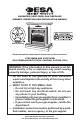
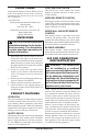
UNVENTED (VENT-FREE) GAS FIREPLACE OWNER’S OPERATION AND INSTALLATION MANUAL Patent Pending Shown with optional cabinet mantel, hearth base and trim accessories. VTGF33NRB AND VTGF33PRB GAS FIREPLACE WITH TOTAL CONTROL SYSTEM (TCS) WARNING: If the information in this manual is not followed exactly, a fire or explosion may result causing property damage, personal injury, or loss of life. — Do not store or use gasoline or other flammable vapors and liquids in the vicinity of this or any other appliance.
WARNING: Improper installation, adjustment, alteration, service, or maintenance can cause injury or property damage. Refer to this manual for correct installation and operational procedures. For assistance or additional information consult a qualified installer, service agency, or the gas supplier. WARNING: This is an unvented gas-fired heater. It uses air (oxygen) from the room in which it is installed. Provisions for adequate combustion and ventilation air must be provided.
SAFETY INFORMATION WARNING: This product contains and/or generates chemicals known to the State of California to cause cancer or birth defects, or other reproductive harm. IMPORTANT: Read this owner’s manual carefully and completely before trying to assemble, operate, or service this heater. Improper use of this heater can cause serious injury or death from burns, fire, explosion, electrical shock, and carbon monoxide poisoning.
SAFETY INFORMATION Continued 1. This appliance is only for use with the type of gas indicated on the rating plate. This appliance is not convertible for use with other gases. 2. Do not place propane/LP supply tank(s) inside any structure. Locate propane/LP supply tank(s) outdoors (propane/LP units only). 3.
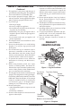
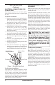
LOCAL CODES PIEZO IGNITION SYSTEM Install and use fireplace with care. Follow all local codes. In the absence of local codes, use the latest edition of The National Fuel Gas Code, ANSI Z223.1/NFPA 54*. *Available from: American National Standards Institute, Inc. 1430 Broadway New York, NY 10018 National Fire Protection Association, Inc. Batterymarch Park Quincy, MA 02269 UNPACKING CAUTION: Do not remove the data plates attached to the heater base assembly.
AIR FOR COMBUSTION AND VENTILATION Continued PROVIDING ADEQUATE VENTILATION The following are excerpts from National Fuel Gas Code, ANSI Z223.1/NFPA 54, Section 5.3, Air for Combustion and Ventilation. All spaces in homes fall into one of the three following ventilation classifications: 1. Unusually Tight Construction 2. Unconfined Space 3. Confined Space The information on pages 5 through 7 will help you classify your space and provide adequate ventilation.
AIR FOR COMBUSTION AND VENTILATION Continued Example: 40,000 Gas water heater _____________ Btu/Hr 33,000 Vent-free fireplace + ____________ Btu/Hr 73,000 Total = ____________ Btu/Hr 4. Compare the maximum Btu/Hr the space can support with the actual amount of Btu/Hr used.
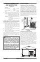
INSTALLATION NOTICE: This heater is intended for use as supplemental heat. Use this heater along with your primary heating system. Do not install this heater as your primary heat source. If you have a central heating system, you may run system’s circulating blower while using heater. This will help circulate the heat throughout the house. In the event of a power outage, you can use this heater as your primary heat source. WARNING: A qualified service person must install fireplace. Follow all local codes.
INSTALLATION REMOVING FIREPLACE SCREEN AND FLOOR ASSEMBLY Continued Carefully follow the instructions below. This will ensure safe installation. Minimum Clearances For Side Combustible Material, Side Wall, and Ceiling A. Clearances from the side of the fireplace cabinet to any combustible material and wall should follow diagram in Figure 5. Example: The face of a mantel, bookshelf, etc. is made of combustible material and protrudes 3 1/2" from the wall.
INSTALLATION RELOCATING WALL SWITCH ASSEMBLY Continued ELECTRICAL CONNECTIONS FOR POWER CORD This fireplace operates on 120 VAC, 60 Hz power. An electrical power cord is supplied with this unit. For Mantel Installation 1. Determine from which side of the fireplace the power cord will exit. Locate the 1.5" diameter hole near the center of floor support bracket on appropriate side of lower cavity (see Figure 7). 2. Locate power cord. Remove wire tie or tape holding plug end of power cord. 3.
INSTALLATION Continued For Mantel Installation If fireplace is to be installed into a mantel, (see Conventional Fireplace Installation, page 16) the wall switch assembly may be mounted on either side of the mantel, facing to the side. Do not locate wall switch assembly anywhere on the front face of the mantel. CAUTION: Be careful of gas lines and wiring when moving floor. 1. Determine the new location for the wall switch assembly. The wires attached to switch are six feet long. 2.
INSTALLATION Continued 11. Using a keyhole saw, hack saw blade, drill, file, or other suitable tool, carefully cut out the rectangular opening. Note: The corners of the rectangle may be round. IMPORTANT: Do not exceed the size of the rectangle on template. 12. From inside the recessed opening for the fireplace, carefully pass wall switch assembly through the rectangular opening to the outside of the wall. 13. Using wall anchors supplied in hardware package, fold wall anchor as shown in Figure 11. 14.
INSTALLATION Continued INSTALLING GAS PIPING TO FIREPLACE LOCATION WARNING: A qualified service person must connect fireplace to gas supply. Follow all local codes. WARNING: For propane/LP units, never connect fireplace directly to propane/LP supply. This fireplace requires an external regulator (not supplied). Install the external regulator between the heater and propane/LP supply. WARNING: For natural gas units, never connect fireplace to private (non-utility) gas wells.
INSTALLATION CONNECTING FIREPLACE TO GAS SUPPLY Continued Apply pipe joint sealant lightly to male NPT threads. This will prevent excess sealant from going into pipe. Excess sealant in pipe could result in clogged fireplace valves. Never use sealant on flare threads. WARNING: Use pipe joint sealant that is resistant to liquid petroleum (LP) gas. We recommend that you install a sediment trap in supply line as shown in Figure 15. Locate sediment trap where it is within reach for cleaning.
INSTALLATION Continued CHECKING GAS CONNECTIONS WARNING: Test all gas piping and connections, internal and external to unit, for leaks after installing or servicing. Correct all leaks at once. WARNING: Never use an open flame to check for a leak. Apply a noncorrosive leak detection fluid to all joints. Bubbles forming show a leak. Correct all leaks at once. WARNING: For propane/LP units, make sure external regulator has been installed between propane/LP supply and heater.
INSTALLATION Continued PRESSURE TESTING FIREPLACE GAS CONNECTIONS 1. Open equipment shutoff valve (see Figure 17, page 15). 2. Open main gas valve located on or near gas meter for natural gas or open propane/LP supply tank valve. 3. Place manual ignition switch in the OFF position. 4. Check all joints from equipment shutoff valve to gas valve (see Figure 18 or 19, page 15). Apply noncorrosive leak detection fluid to all joints. Bubbles forming show a leak. 5. Correct all leaks at once. 6.
INSTALLATION Continued 8. Place cardboard or other protective material on top of hearth base. Carefully set fireplace on protective material, with back of fireplace inside mantel opening. 9. Attach flexible gas line to fireplace gas regulator. See Connecting Fireplace to Gas Supply, page 14. 10. Route electrical cord(s) through access holes in either side of fireplace with bushing. Plug electrical cord(s) into electrical outlet. 11. Carefully insert fireplace into cabinet mantel (see Figure 23).
INSTALLATION Mantel Clearances for Built-In Installation If placing mantel above built-in fireplace, you must meet minimum clearance between mantel shelf and top of fireplace opening. Continued Nails or Wood Screws NOTICE: Surface temperatures of adjacent walls and mantels become hot during operation. Walls and mantels above the firebox may become hot to the touch. If installed properly, these temperatures meet the requirement of the national product standard.
INSTALLATION Trim Hanging Screws Continued ASSEMBLING AND ATTACHING OPTIONAL PERIMETER TRIM (Included with Mantel Accessory) Note: The instructions below show assembling and attaching trim to fireplace. 1. Remove packaging from three pieces of trim. 2. Locate four screws, two adjusting plates with set screws, and two shims in the hardware packet. 3. Align shim under adjusting plate as shown in Figure 28. 4. Slide one end of adjusting plate/shim in slot on mitered edge of top trim (see Figure 28). 5.
INSTALLATION Continued INSTALLING LOGS WARNING: Failure to position the parts in accordance with these diagrams or failure to use only parts specifically approved with this heater may result in property damage or personal injury. CAUTION: After installation and periodically thereafter, check to ensure that no yellow flame comes in contact with any log. With the heater set to HI, check to see if flames contact any log. If so, reposition logs according to the log installation instructions in this manual.
INSTALLATION OPERATING FIREPLACE Continued INSTALLING BATTERY INTO REMOTE 1. Locate slot at bottom of remote control (see Figure 35). Firmly insert tool such as a small screwdriver, butter knife, or dime into the slot and lift up to remove cover. 2. Insert supplied battery into remote control. Positive and negative are marked inside remote control casing. Note: Remote will not function if battery is not installed correctly. 3. Slide tab on cover into remote housing and snap cover back into place.
OPERATING FIREPLACE Continued NORMAL LIGHTING INSTRUCTIONS WARNING: You must operate this heater with the fireplace screen in place. Make sure fireplace screen is in place before running heater. NOTICE: During initial operation of new heater, burning logs will give off a paper-burning smell. Open damper or window to vent smell. This will only last a few hours. 1. STOP! Read the safety information, page 21. 2. Make sure equipment shutoff valve is fully open. 3. Wait five (5) minutes to clear out any gas.
OPERATING FIREPLACE Continued Note: You may be running this heater for the first time after connecting to gas supply or at the start of your heating season. If so, the ON button may need to be pressed again. This will allow air to bleed from gas system. If several attempts to light pilot fail, contact a qualified service person or gas supplier for repairs. Until repairs are made, light and operate manually (see Manual Lighting Instructions for Electrical Power Outage). 4.
OPERATING FIREPLACE INSPECTING BURNERS Continued Check pilot flame pattern and burner flame patterns often. TO TURN OFF GAS TO APPLIANCE PILOT FLAME PATTERN Shutting Off Heater When Manually Lit Set manual ignition bypass switch on control panel to OFF (automatic ignition position). This will cause the controls to shut down the fireplace. OPTIONAL BLOWER OPERATION Locate the blower switch by opening lower louver on fireplace. Blower switch is located at lower left inside louver door.
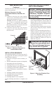
INSPECTING BURNERS Continued BURNER FLAME PATTERNS Figure 43 shows correct front and/or middle burner flame patterns. Figure 44 shows incorrect front and/or middle burner flame patterns. The incorrect burner flame patterns show yellow tipping at top of blue flame. WARNING: If yellow tipping occurs, your heater could produce increased levels of carbon monoxide. If burner flame patterns show yellow tipping, follow instructions below. Yellow flame on rear burner is normal.
CLEANING AND MAINTENANCE Pilot Bracket Continued 3. Blow air through the ports/slots and holes in the burners. 4. Check the injector holders located at the end of the burner tubes again. Remove any large particles of dust, dirt, lint, or pet hair with a soft cloth or vacuum cleaner nozzle. 5. Blow air into the primary air holes on the injector holders. 6. In case any large clumps of dust have now been pushed into the burner repeat steps 3 and 4. Clean the pilot assembly also.
TROUBLESHOOTING WARNING: Turn off heater and let cool before servicing. Only a qualified service person should service and repair heater. CAUTION: Never use a wire, needle, or similar object to clean ODS/pilot. This can damage ODS/pilot unit. Note: All troubleshooting items are listed in order of operation. OBSERVED PROBLEM POSSIBLE CAUSE When buttons on remote control are pressed, there is no response from fireplace 1. Battery in remote control 1.
TROUBLESHOOTING Continued OBSERVED PROBLEM POSSIBLE CAUSE Burner backfiring during 1. Burner orifice is clogged or combustion damaged 2. Damaged burner 3. Gas regulator defective Slight smoke or odor during initial 1. Not enough air operation 2. Gas regulator defective 3. Residues from manufacturing processes and logs curing REMEDY 1. Clean burner (see Cleaning and Maintenance, page 25) or replace burner orifice 2. Replace damaged burner 3. Replace regulator 1. Check burner for dirt and debris.
TROUBLESHOOTING Continued OBSERVED PROBLEM POSSIBLE CAUSE When ignitor button is pressed, 1. Gas supply turned off or there is spark at ODS/pilot but no equipment shutoff valve ignition (manual ignition mode) closed 2. Control knob not in PILOT position 3. Air in gas lines when installed 4. Depleted gas supply (propane/LP only) 5. ODS/pilot is clogged 6. Gas regulator setting is not correct ODS/pilot lights but flame goes 1.
TROUBLESHOOTING Continued WARNING: If you smell gas • Shut off gas supply. • Do not try to light any appliance. • Do not touch any electrical switch; do not use any phone in your building. • Immediately call your gas supplier from a neighbor’s phone. Follow the gas supplier’s instructions. • If you cannot reach your gas supplier, call the fire department. IMPORTANT: Operating fireplace where impurities in air exist may create odors.
TROUBLESHOOTING Continued OBSERVED PROBLEM POSSIBLE CAUSE REMEDY Dark residue on logs or inside of fireplace Note: After removng all causes of residue deposits, completely clean fireplace and appliances of all residue before reusing appliance. 1. Improper log placement 1. Properly locate logs (see Installing Logs, page 20) 2. Eliminate source of drafts around heater 3. Clean out air holes at burner inlet. Periodically repeat as needed 4. Remove blockage 2.
ILLUSTRATED PARTS BREAKDOWN REMOTE CONTROL LOG BASE ASSEMBLY MODELS VTGF33PRB AND VTGF33NRB (SHOWN) 59 60 32 www.desatech.
PARTS LIST REMOTE CONTROL LOG BASE ASSEMBLY MODELS VTGF33PRB AND VTGF33NRB This list contains replaceable parts used in your fireplace. When ordering parts, follow the instructions listed under Replacement Parts on page 31 of this manual. KEY PART NO.
ILLUSTRATED PARTS BREAKDOWN FIREPLACE MODELS VTGF33NRB AND VTGF33PRB 9 23 24 1 2 3 4 5 9 22 6 7 10 11 10 9 8 12 13 15 16 18 21 9 14 15 19 20 18 17 34 www.desatech.
PARTS LIST FIREPLACE MODELS VTGF33NRB AND VTGF33PRB This list contains replaceable parts used in your fireplace. When ordering parts, follow the instructions listed under Replacement Parts on page 31 of this manual. KEY NO.
ACCESSORIES NOTICE: All accessories may not be available for all fireplace models. Purchase these fireplace accessories from your local dealer. If they can not supply these accessories, call DESA Heating Products at 1-866-672-6040 for information. You can also write to the address listed on the back page of this manual. CORNER HEARTH BASE G3008F Series - Walnut Finished G3009U Series - Unfinished G3010F Series - Oak Finished For all models.
ACCESSORIES Continued Mantel Trim CABINET MANTEL AND FULL HEARTH BASE GMC90F Series - Oak Finished GMC91U Series - Unfinished Birch GMC92F Series - Cherry Finished Birch For all models. Mantel features columns, moldings, fluting and medallion. Tree-sided perimeter trim included. Dimensions (WxHxD): 56" x 50" x 24" SLIM HEARTH BASE (Not Shown) G3005J Series - Jade Marble Laminate G3005S Series - Sandstone Marble Laminate G3005B Series - Black Onyx Marble Laminate For all models.
ACCESSORIES WALL-MOUNT THERMOSTAT SWITCH - GWMT1 (Not Shown) Continued For all models. The desired comfort setting can be selected on the wall thermostat and the fireplace will automatically cycle from pilot to the heat setting selected. WALL-MOUNT ON/OFF SWITCH GWMS2 (Not Shown) RECEIVER AND HAND-HELD THERMOSTAT REMOTE CONTROL KIT - GHRCTB For all models. Allows the gas fireplace to be turned on and off with a wall switch. For all Remote-Ready Models.
TEMPLATES 3/8" Diameter 2 Holes 1/8" Diameter 2 Holes 3/4" 3/4" 4 3/4" CUT HERE 4 3/4" 3 3/4" 3 3/4" 3/8" 3/8" 3/16" Template 1 - Relocating Wall Switch to Hollow Room Wall 113134-01B Template 2 - Relocating Wall Switch to Side Wall of Mantel www.desatech.
THIS PAGE INTENTIONALLY LEFT BLANK 40 www.desatech.
113134-01B POWER CORD GREEN www.desatech.com BROWN BLUE BLACK WHITE GREEN/YELLOW SENSOR MODULE RECEIVER PIEZO MANUAL OVERRIDE SWITCH INDICATION BOARD VALVE 3 2 1 FAN SWITCH WHITE RED BLUE BLOWER ELECTRODE IGNITOR Note: For proper operation, the wires must be connected exactly as shown in wiring diagram.
NOTES _____________________________________________________ ______________________________________________________ ______________________________________________________ ______________________________________________________ ______________________________________________________ ______________________________________________________ ______________________________________________________ ______________________________________________________ ______________________________________________________ ___________
NOTES _____________________________________________________ ______________________________________________________ ______________________________________________________ ______________________________________________________ ______________________________________________________ ______________________________________________________ ______________________________________________________ ______________________________________________________ ______________________________________________________ ___________
WARRANTY INFORMATION KEEP THIS WARRANTY Model Serial No. Date Purchased Always specify model and serial numbers when communicating with the factory. We reserve the right to amend these specifications at any time without notice. The only warranty applicable is our standard written warranty. We make no other warranty, expressed or implied.