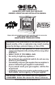
UNVENTED (VENT-FREE) GAS FIREPLACE OWNER’S OPERATION AND INSTALLATION MANUAL Shown with optional cabinet mantel with hearth base and trim accessories. VSGF33PRC AND VSGF33NRC Remote-ready fireplace System WARNING: If the information in this manual is not followed exactly, a fire or explosion may result causing property damage, personal injury, or loss of life. — Do not store or use gasoline or other flammable vapors and liquids in the vicinity of this or any other appliance.
TABLE OF CONTENTS Safety Information................................................ 3 Product Identification............................................ 4 Local Codes......................................................... 5 Unpacking............................................................ 5 Product Features.................................................. 5 Air For Combustion and Ventilation...................... 5 Installation............................................................
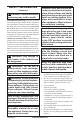
SAFETY INFORMATION Continued DANGER: Carbon monoxide poisoning may lead to death! Carbon Monoxide Poisoning: Early signs of carbon monoxide poisoning resemble the flu, with headaches, dizziness, or nausea. If you have these signs, the heater may not be working properly. Get fresh air at once! Have heater serviced. Some people are more affected by carbon monoxide than others.
SAFETY INFORMATION Continued 6. Do not add extra logs or ornaments such as pine cones, vermiculite, or rock wool. Using these added items can cause sooting. Do not add lava rock around base. Rock and debris could fall into the control area of fireplace. 7. To prevent the creation of soot, follow the instructions in Cleaning and Maintenance, page 21. 8. Before using furniture polish, wax, carpet cleaner, or similar products, turn heater off.
Local Codes Safety Device Continued State of Massachusetts: The installation must be made by a licensed plumber or gas fitter in the Commonwealth of Massachusetts. Sellers of unvented propane or natural gas-fired supplemental room heaters shall provide to each purchaser a copy of 527 CMR 30 upon sale of the unit. Vent-free gas products are prohibited for bedroom and bathroom installation in the Commonwealth of Massachusetts.
AIR FOR COMBUSTION AND VENTILATION Continued While it is good to make your home energy efficient, your home needs to breathe. Fresh air must enter your home. All fuel-burning appliances need fresh air for proper combustion and ventilation. Exhaust fans, fireplaces, clothes dryers, and fuel burning appliances draw air from the house to operate. You must provide adequate fresh air for these appliances. This will insure proper venting of vented fuel-burning appliances.
AIR FOR COMBUSTION AND VENTILATION Continued Example: 40,000 Gas water heater _______________ Btu/Hr 33,000 Vent-free fireplace +______________ Btu/Hr 73,000 Total =______________ Btu/Hr 4. Compare the maximum Btu/Hr the space can support with the actual amount of Btu/Hr used.
Installation NOTICE: This heater is intended for use as supplemental heat. Use this heater along with your primary heating system. Do not install this heater as your primary heat source. If you have a central heating system, you may run system’s circulating blower while using heater. This will help circulate the heat throughout the house. In the event of a power outage, you can use this heater as your primary heat source. WARNING: A qualified service person must install fireplace. Follow all local codes.
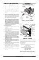
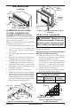
Installation Trim Hanging Screws Continued Rail Hood Hanging Notches on Trim Screw Figure 5 - Installing Hood Assembling and attaching OPTIONAL perimeter trim (Included with Mantel Accessory) IMPORTANT: If you are recessing the firebox in a wall, do not attach trim at this time. See Built-In Fireplace Installation, page 11. Note: The instructions below show assembling and attaching trim to fireplace. 1. Remove packaging from three pieces of trim. 2.
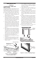
Installation Continued Conventional Fireplace Installation Conventional installation of this fireplace involves installing fireplace along with the corner, face, or cabinet mantel with hearth base accessories against a wall in your home. Follow the instructions in this section to install the fireplace in this manner. 1. Assemble cabinet mantel, hearth base, and trim accessories. Assembly instructions are included with each accessory. 2.
5. Carefully insert fireplace into rough opening. 6. Attach flexible gas line to gas supply. See Connecting Fireplace to Gas Supply, page 14. 7. Attach fireplace to wall studs using nails or wood screws through holes in nailing flange (see Figure 15). 8. Check all gas connections for leaks. See Checking Gas Connections, page 15. 9. Plug electrical cord into electrical outlet installed in step 2. 10. Install trim after final finishing and/or painting of wall (see Figure 7, page 9).
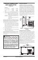
Installation Installing Gas Piping to Fireplace Location Continued Mantel Clearances for Built-In Installation If placing mantel above built-in fireplace, you must meet minimum clearance between mantel shelf and top of fireplace opening. Notice: If your installation does not meet the minimum clearances shown, you must do one of the following: • raise the mantel to an acceptable height • remove the mantel NOTICE: Surface temperatures of adjacent walls and mantels become hot during operation.
Installation Continued For propane/LP units, the installer must supply an external regulator. The external regulator will reduce incoming gas pressure. You must reduce incoming gas pressure to between 11" and 14" of water. If you do not reduce incoming gas pressure, heater regulator damage could occur. Install external regulator with the vent pointing down as shown in Figure 17. Pointing the vent down protects it from freezing rain or sleet. CAUTION: Use only new, black iron or steel pipe.
Installation Continued CONNECTING Fireplace to Gas Supply Installation Items Needed • 5/16" hex socket wrench or nut-driver • Phillips screwdriver • sealant (resistant to propane/LP gas, not provided) 1. Remove fireplace screen. Remove two screws that hold fireplace screen in place for shipping. These screws are located near top of screen. Discard screws. Lift fireplace screen up and pull out to remove. 2. Remove screws that attach log base assembly to fireplace (see Figure 19).
Installation Open Continued CAUTION: Make sure external regulator has been installed between propane/LP supply and fireplace. See guidelines under Connecting Fireplace to Gas Supply, page 14. Equipment Shutoff Valve Closed Figure 21 - Equipment Shutoff Valve Equipment Shutoff Valve Pressure Testing Gas Supply Piping System Test Pressures In Excess Of 1/2 PSIG (3.5 kPa) 1. Disconnect fireplace with its main gas valve (control valve) and equipment shutoff valve from gas supply piping system.
Installation Front Left Log Continued Rear Log INSTALLING LOGS WARNING: Failure to position the parts in accordance with these diagrams or failure to use only parts specifically approved with this heater may result in property damage or personal injury. CAUTION: Do not remove the data plates attached to the heater base assembly. The data plates contain important safety and warranty information. It is very important to install these logs exactly as instructed. Do not modify logs.
WARNING: If you do not follow these instructions exactly, a fire or explosion may result causing property damage, personal injury or loss of life. A. This appliance has a pilot which must be lighted by hand. When lighting the pilot, follow these instructions exactly. B. BEFORE LIGHTING smell all around the appliance area for gas. Be sure to smell next to the floor because some gas is heavier than air and will settle on the floor. WHAT TO DO IF YOU SMELL GAS • Do not try to light any appliance.
OPERATING fireplace TO TURN OFF GAS TO APPLIANCE Continued 7. With control knob pressed in, press and release ignitor button. This will light pilot. The pilot is attached to the front burner. If needed, keep pressing ignitor button until pilot lights. Note: If pilot does not stay lit, contact a qualified service person or gas supplier for repairs. Until repairs are made, light pilot with match. To light pilot with match, see Manual Lighting Procedure. 8.
OPERATING fireplace Continued Flame Adjustment Knob F T ON LO PI L O Selector Switch in Remote Position (Optional HandHeld Remote Control) OF ON OFF REMOTE HI Control Knob in On Position Figure 30 - Setting the Selector Switch, Control Knob, and Flame Adjustment Knob for Hand-Held Remote Operation On/Off Model HRC100 Hold the control button on the hand-held remote until burner turns on. Hold the control button again until burner turns off (see Figure 31).
OPERATING fireplace Continued 2. The receiver continuously receives signals from the hand-held remote to control the room temperature. If the hand-held remote is misplaced, obstructed, or for any reason cannot transmit to the receiver, the receiver will shut off the fireplace after 8 minutes. Key Pad Lock Feature This feature allows the user to lock/unlock the keypad on the hand-held remote in the MANU or AUTO mode to prevent inadvertent operation (i.e. children operating the hand-held remote control, etc.
INSPECTING BURNERS Continued NOTICE: Do not mistake orange flames with yellow tipping. Dirt or other fine particles are burned by fireplace, causing brief patches of orange flame. Figure 35 shows correct front burner flame pattern. Figure 36 shows incorrect front burner flame pattern. The incorrect burner flame pattern shows yellow tipping at top of blue flame.
CLEANING AND MAINTENANCE Wiring Diagram Continued 6. In case any large clumps of dust have now been pushed into the burner repeat steps 3 and 4, page 21. Clean the pilot assembly also. A yellow tip on the pilot flame indicates dust and dirt in the pilot assembly. There is a small pilot air inlet hole about 2" from where the pilot flame comes out of the pilot assembly (see Figure 38). With the unit off, lightly blow air through the air inlet hole.
Troubleshooting WARNING: Turn off heater and let cool before servicing. Only a qualified service person should service and repair heater. CAUTION: Never use a wire, needle, or similar object to clean ODS/pilot. This can damage ODS/pilot unit. Note: All troubleshooting items are listed in order of operation. OBSERVED PROBLEM POSSIBLE CAUSE REMEDY When ignitor button is pressed, 1. Ignitor electrode not con- 1. Reconnect ignitor cable there is no spark at ODS/pilot nected to ignitor cable 2.
TROUBLESHOOTING Continued OBSERVED PROBLEM POSSIBLE CAUSE REMEDY ODS/pilot lights but flame goes out when control knob is released 1. Control knob not fully pressed in 2. Control knob not pressed in long enough 3. Equipment shutoff valve not fully open 4. Pilot flame not touching thermocouple, which allows thermocouple to cool, causing pilot flame to go out. This problem could be caused by one or both of the following: A) Low gas pressure B) Dirty or partially clogged ODS/pilot 5.
TROUBLESHOOTING Continued OBSERVED PROBLEM POSSIBLE CAUSE Moisture/condensation noticed on windows 1. Not enough combustion/ven- 1. Refer to Air for Combustion tilation air and Ventilation requirements (page 5) Heater produces a whistling noise when burners are lit 1. Turning control knob to HI po- 1. Turn control knob to LO position sition when burners are cold and let warm up for a minute 2. Air in gas line 2. Operate burners until air is removed from line.
TROUBLESHOOTING Continued WARNING: If you smell gas • Shut off gas supply. • Do not try to light any appliance. • Do not touch any electrical switch; do not use any phone in your building. • Immediately call your gas supplier from a neighbor’s phone. Follow the gas supplier’s instructions. • If you cannot reach your gas supplier, call the fire department. IMPORTANT: Operating fireplace where impurities in air exist may create odors.
Replacement Parts Note: Use only original replacement parts. This will protect your warranty coverage for parts replaced under warranty. Parts Under Warranty Contact authorized dealers of this product. If they can’t supply original replacement part(s), call DESA Heating Products’ Technical Service Department at 1-866-672-6040.
Illustrated Parts Breakdown Log Base Assembly Models VSGF33NRC and VSGF33PRC 1c 1e 1b 1a 1f 1d 7 5 8 LPG 9 6 30 24 10 4 12 14 4 18 3 4 28 (NG Only) 4 25 19 26 15 13 16 29 (NG Only) 22 16 13 20 23 21 17 28 www.desatech.
Parts List 1a 1b 1c 1d 1e 1f 2 3 4 5 6 7 8 9 10 11 12 13 14 15 16 17 18 19 20 21 22 23 24 25 26 27 28 29 30 113621-08 113621-09 113621-10 113621-11 113621-12 113621-07 099387-09 099387-12 M11084-38 098304-01 103779-01 103778-01 098249-01 112713-03 112465-02 112466-02 112705-03 098271-12 ** 111435-01 101004-08 101004-01 104241-02 103782-01 103284-03 112708-05 097809-02 M12461-26 098265-02 103781-01 103781-02 099998-01 101004-14 101004-15 101628-03 M11084-38 901056-01 099387-14 099918-02 M11084-26 DESCRIPT
ILLUSTRATED PARTS BREAKDOWN Fireplace mOdels VSGF33NRC and VSGF33PRC 7 17 1 6 9 12 2 16 4 8 3 16 11 14 11 16 16 16 15 11 5 7 16 18 10 16 10 13 30 www.desatech.
PARTS LIST Fireplace Models VSGF33NRC and VSGF33PRC This list contains replaceable parts used in your fireplace. When ordering parts, follow the instructions listed under Replacement Parts on page 27 of this manual. KEY NO. PART NO.
Accessories Notice: All accessories may not be available for all fireplace models. Purchase these fireplace accessories from your local dealer. If they can not supply these accessories, call DESA Heating Products at 1-866-672-6040 for information. You can also write to the address listed on the back page of this manual. EQUIPMENT SHUTOFF VALVE GA5010 For all models. Equipment shutoff valve with 1/8" NPT tap. Fits 1/2" NPT pipe.
ACCESSORIES CLEANING KIT - GCK (Not Shown) Continued WALL-MOUNT THERMOSTAT SWITCH - GWMT1 (Not Shown) For all models. The desired comfort setting can be selected on the wall thermostat and the fireplace will automatically cycle from pilot to the heat setting selected. WALL-MOUNT ON/OFF SWITCH GWMS2 (Not Shown) For all models. Your vent-free gas appliance requires regular cleaning and maintenance to prevent performance problems.
NOTES _____________________________________________________ ______________________________________________________ ______________________________________________________ ______________________________________________________ ______________________________________________________ ______________________________________________________ ______________________________________________________ ______________________________________________________ ______________________________________________________ ___________
NOTES _____________________________________________________ ______________________________________________________ ______________________________________________________ ______________________________________________________ ______________________________________________________ ______________________________________________________ ______________________________________________________ ______________________________________________________ ______________________________________________________ ___________
Warranty Information KEEP THIS WARRANTY Model Serial No. Date Purchased Always specify model and serial numbers when communicating with the factory. We reserve the right to amend these specifications at any time without notice. The only warranty applicable is our standard written warranty. We make no other warranty, expressed or implied.