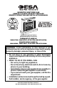
UNVENTED (VENT-FREE) GAS COMPACT CLASSIC HEARTH® FIREPLACE OWNER’S OPERATION AND INSTALLATION MANUAL Patent Pending Shown with Optional Cabinet Mantel/Hearth Base Accessory THERMOSTAT MODELS: VMH10TNC, VMH10TPC, EFS10TPA AND EFS10TNA REMOTE-READY MODELS: VMH10RNC, VMH10RPC, EFS10RPA AND EFS10RNA WARNING: If the information in this manual is not followed exactly, a fire or explosion may result causing property damage, personal injury, or loss of life.
WARNING: Improper installation, adjustment, alteration, service, or maintenance can cause injury or property damage. Refer to this manual for correct installation and operational procedures. For assistance or additional information consult a qualified installer, service agency, or the gas supplier. WARNING: This is an unvented gas-fired heater. It uses air (oxygen) from the room in which it is installed. Provisions for adequate combustion and ventilation air must be provided.
SAFETY INFORMATION WARNING: This product contains and/or generates chemicals known to the State of California to cause cancer or birth defects, or other reproductive harm. IMPORTANT: Read this owner’s manual carefully and completely before trying to assemble, operate, or service this fireplace. Improper use of this fireplace can cause serious injury or death from burns, fire, explosion, electrical shock, and carbon monoxide poisoning.
SAFETY INFORMATION Continued 1. This appliance is only for use with the type of gas indicated on the rating plate. This appliance is not convertible for use with other gases. 2. Do not place propane/LP supply tank(s) inside any structure. Locate propane/LP supply tank(s) outdoors. 3. If you smell gas • shut off gas supply • do not try to light any appliance • do not touch any electrical switch; do not use any phone in your building • immediately call your gas supplier from a neighbor’s phone.
PRODUCT IDENTIFICATION UNPACKING Fireplace Cabinet Logs 1. Remove fireplace and hood from carton. Log is wrapped and inside fireplace. Do not remove at this time. 2. Remove all protective packaging applied to fireplace for shipment. 3. Make sure your fireplace includes one hardware packet. 4. Check fireplace for any shipping damage. If fireplace is damaged, promptly inform dealer where you bought fireplace.
ASSEMBLY WARNING: Always have screen in place before operating fireplace. This prevents excessive temperatures on fireplace surfaces. WARNING: Failure to position the parts in accordance with these diagrams or failure to use only parts specifically approved with this fireplace may result in property damage or personal injury. 4. Locate four black phillips sheet metal screws from the hardware packet. 5. Rotate hood as shown in Figure 3. Make sure hood tabs point toward fireplace. 6.
AIR FOR COMBUSTION VENTILATION WARNING: This fireplace shall not be installed in a confined space or unusually tight construction unless provisions are provided for adequate combustion and ventilation air. Read the following instructions to insure proper fresh air for this and other fuel-burning appliances in your home. Today’s homes are built more energy efficient than ever. New materials, increased insulation, and new construction methods help reduce heat loss in homes.
AIR FOR COMBUSTION AND VENTILATION Continued DETERMINING FRESH-AIR FLOW FOR FIREPLACE LOCATION Determining if You Have a Confined or Unconfined Space Use this work sheet to determine if you have a confined or unconfined space. Space: Includes the room in which you will install fireplace plus any adjoining rooms with doorless passageways or ventilation grills between the rooms. 1. Determine the volume of the space (length x width x height). Length x Width x Height =__________cu. ft.
AIR FOR COMBUSTION AND VENTILATION Continued IMPORTANT: Do not provide openings for inlet or outlet air into attic if attic has a thermostat-controlled power vent. Heated air entering the attic will activate the power vent. 12" Ventilation Grills into Adjoining Room, Option 1 Ventilation Grills Into Adjoining Room, Option 2 Or Remove Door into Adjoining Room, Option 3 INSTALLATION NOTICE: This heater is intended for use as supplemental heat. Use this heater along with your primary heating system.
INSTALLATION Continued IMPORTANT: Vent-free fireplaces add moisture to the air. Although this is beneficial, installing fireplace in rooms without enough ventilation air may cause mildew to form from too much moisture. See Air for Combustion and Ventilation, page 7. Note: Your fireplace is designed to be used in zero clearance installations.
INSTALLATION Continued Minimum Clearances For Side Combustible Material, Side Wall, and Ceiling A. Clearances from the side of the fireplace cabinet to any combustible material and wall should follow diagram in Figure 6. Example: The face of a mantel, bookshelf, etc. is made of combustible material and protrudes 3 1/2" from the wall. This combustible material must be 4" from the side of the fireplace opening (see Figure 6). B.
INSTALLATION Continued 3. Install gas piping to fireplace location. This installation includes an approved flexible gas line (if allowed by local codes) after the equipment shutoff valve. The flexible gas line must be the last item installed on the gas piping. 4. If you have not assembled firebox, follow instructions on page 6. 5. Carefully set fireplace in front of rough opening with back of fireplace inside wall opening. 6. Attach flexible gas line to fireplace gas regulator.
INSTALLATION Continued Mantel Shelf 21" 16" 19" 13" 10" Note: 8" All vertical measurements 6" are from top of 2 1/2" fireplace opening to bottom of mantel shelf. All measurements are in inches. 10. Attach wood base to floor with two 1 3/4" black screws provided (see Figure 12). If the floor is concrete use anchor method (see Attaching Wood Base to Solid Floor, page 17). 11. Install gas line. See Connecting To Gas Supply, page 17. 12. Check for leaks. See Checking Gas Connections, page 19. 13.
Blower Bracket Mounting Holes INSTALLATION Continued Assembling Trim (Trim shipped with mantel) 1. Remove packaging from three remaining pieces of trim. 2. Locate two adjusting plates with set screws, and two shims in the hardware packet. 3. Align shim under adjusting plate as shown in Figure 13. 4. Slide one end of adjusting plate/shim in slot on mitered edge of top trim (see Figure 13). 5. Slide other end of adjusting plate/shim in slot on mitered edge of side trim (see Figure 13). 6.
INSTALLATION Continued Blower Bracket Assembly Screw Wire Harness Wiring Routing Hole in Baffle Baffle Blower Mounting Holes Switch Power Cord Snap Bushing 3 2 1 Switch Plate Blue Black Red Front Fan Wire Harness Switch Rear Fan Cover Switch Cover Lower Louver Door Figure 15 - Installing Blower (Thermostat Unit Shown) 6. In top of the fireplace cabinet, locate the four mounting holes on the outer casing. Align these four holes with those on the blower bracket assembly.
Blower Motor Continued 10. Route power cord out of the cabinet by inserting it through the bushing on the outer casing (see Figure 15, page 15). Plug fan kit into 120-Volt grounded power supply and test operation. Note: When switch is in the AUTO position, the fan will start after the fireplace has run for a few moments. The fan will continue to run for several moments after the fireplace has been turned off. When switch is in the ON position, the fan will run until turned to OFF.
INSTALLATION Continued Wire Harness Blower Bracket Assembly Screw Clamp Connector (not included) Switch Power Cord 3 2 1 Switch Plate Red Blue Black Plastic Wire Strap Wire Harness Outlet Receptacle (not included) Lower Louver Door Figure 19 - Installing Blower (Thermostat Unit Shown) ATTACHING WOOD BASE TO SOLID FLOOR For attaching base to solid floors (concrete or masonry) Note: Floor anchors and mounting screws are in hardware package. The hardware package is provided with fireplace. 1.
INSTALLATION Continued IMPORTANT: For natural gas, check gas line pressure before connecting fireplace to gas line. Gas line pressure must be no greater than 14 inches of water. If gas line pressure is higher, heater regulator damage could occur. CAUTION: Never connect propane/LP fireplace directly to the propane/LP supply. This fireplace requires an external regulator (not supplied). Install the external regulator between the fireplace and propane/LP supply.
Continued CONNECTING FIREPLACE TO GAS SUPPLY Installation Items Needed • Phillips screwdriver • sealant (resistant to propane/LP gas, not provided) NOTICE: Most building codes do not permit concealed gas connections. A flexible gas line is provided to allow accessibility from the fireplace (see Figure 1, page 5). The flexible gas supply line connection to the equipment shutoff valve should be accessible. 1.
INSTALLATION Continued 3. Pressurize supply piping system by either opening propane/LP supply tank valve for propane/LP gas or opening main gas valve located on or near gas meter for natural gas, or using compressed air. 4. Check all joints of gas supply piping system. Apply noncorrosive leak detection fluid to all joints. Bubbles forming show a leak. 5. Correct all leaks at once. 6. Reconnect fireplace and equipment shutoff valve to gas supply. Check reconnected fittings for leaks.
INSTALLATION Remote Receiver Continued OPTIONAL WIRELESS HAND-HELD REMOTE CONTROL ACCESSORIES Remote-Ready Models Only (GHRCB Series & GHRCTB Series) Installing Receiver 1. Disconnect jumper wire from control valve (see Figure 27). 2. Locate battery clip mounted on back of receiver (see Figure 28). 3. Slide 9-volt battery (not included) through clip. 4. Attach terminal wires to battery (see Figure 29). 5. Connect wires from remote receiver to control valve as shown in Figure 29. 6.
INSTALLATION Continued OPTIONAL WALL MOUNTED THERMOSTAT - GWMT1 (Remote-Ready Models Only) WARNING: Read and follow installation instructions. Installation should be done by a qualified installer familiar with lowvoltage wiring procedures. WARNING: Do not connect this thermostat to any electrical source! Electrical shock and/or fire hazard will occur. 1. Disconnect jumper wire from control valve (see Figure 32). 2. Connect one terminal of 25 ft. wire to "TPTH" terminal on control valve (see Figure 32). 3.
Shoulder Screw INSTALLATION Continued Log OPTIONAL WALL SWITCH - GWMS2 (Remote-Ready Models Only) WARNING: Read and follow installation instructions. Installation should be done by a qualified installer familiar with lowvoltage wiring procedures. WARNING: Do not connect this switch to any electrical source! Electrical shock and/or fire hazard will occur. 1. Connect one terminal of 25 ft. wire to "TPTH" terminal on control valve (see Figure 32, page 22). 2.
OPERATING FIREPLACE Continued D. Do not use this appliance if any part has been under water. Immediately call a qualified service technician to inspect the appliance and to replace any part of the control system and any gas control which has been under water. LIGHTING INSTRUCTIONS WARNING: You must operate this fireplace with the screen in place. Make sure fireplace screen is installed before running fireplace.
OPERATING FIREPLACE Continued TO TURN OFF GAS TO APPLIANCE Shutting Off Fireplace 1. Turn control knob clockwise to the OFF position. 2. Turn off all electric power to the appliance (if applicable) if service is to be performed. to the pilot position, the blower will continue to run. The blower will shut off after the firebox temperature decreases. Note: It is safe to operate fireplace with blower turned off. However, the blower helps distribute heated air from the fireplace.
LIGHTING INSTRUCTIONS WARNING: You must operate this fireplace with the fireplace screen in place. Make sure fireplace screen is installed before running fireplace. NOTICE: During initial operation of new fireplace, burning logs will give off a paper-burning smell. Open window to vent smell. This will only last a few hours. WARNING: Burner will come on automatically within one minute when control valve is in the ON position after the pilot is lit. 1. STOP! Read the safety information above. 2.
Shutting Off Fireplace 1. Turn control knob clockwise to the OFF position. 2. If Using Optional Hand-Held Remote: Set remote switch to the OFF position to prevent draining battery. Clockwise Shutting Off Burner Only (pilot stays lit) You may shut off the burner and keep the pilot lit by doing one of the following: 1. Turn control knob clockwise to the PILOT position. 2. If Using Optional Hand-Held Remote: Use remote control manual OFF button.
OPERATING FIREPLACE Continued THERMOSTAT SERIES (MODEL GHRCTB) The hand-held remote can be operated using either the manual mode (MANU) or thermostatic mode (AUTO) (see Figure 45). To select Fahrenheit/Centigrade mode display, carefully press the ˚C/˚F mode button with the end of a paper clip or similar blunt object. Manual Mode 1. Press the POWER and LOCK buttons together to turn on the hand-held remote control. 2. Press the MANU button to turn on the fireplace. 3.
OPERATING FIREPLACE Pilot Burner Continued OPERATING BLOWER This blower has three settings: ON, OFF, and AUTO. In the ON position, the blower will operate constantly. In the OFF position, the blower will not operate. In the AUTO position, the blower will start when the thermostat senses a sufficient increase in firebox temperature. Note: Your fireplace and thermostat blower will not turn on and off at the same time. The fireplace may run for several minutes before the blower turns on.
CLEANING AND MAINTENANCE WARNING: Turn off fireplace and let cool before cleaning. CAUTION: You must keep control areas, burner, and circulating air passageways of fireplace clean. Inspect these areas of fireplace before each use. Have fireplace inspected yearly by a qualified service person. Fireplace may need more frequent cleaning due to excessive lint from carpeting, pet hair, bedding material, etc.
TROUBLESHOOTIING WARNING: Turn off and unplug fireplace and let cool before servicing. Only a qualified service person should service and repair fireplace. CAUTION: Never use a wire, needle, or similar object to clean ODS/pilot. This can damage ODS/pilot unit. Note: All troubleshooting items are listed in order of operation. OBSERVED PROBLEM POSSIBLE CAUSE REMEDY When ignitor button is pressed, there is no spark at ODS/pilot 1. Ignitor electrode not connected to ignitor cable 2.
TROUBLESHOOTING Continued OBSERVED PROBLEM POSSIBLE CAUSE ODS/pilot lights but flame goes out when control knob is released 1. Control knob not fully 1. Press in control knob fully pressed in 2. Control knob not pressed in 2. After ODS/pilot lights, keep conlong enough trol knob pressed in 30 seconds 3. Safety interlock system has 3. Wait one minute for safety inbeen triggered terlock system to reset. Repeat ignition operation 4. Equipment shutoff valve not 4.
TROUBLESHOOTING Continued OBSERVED PROBLEM POSSIBLE CAUSE Slight smoke or odor during initial operation 1. Residues from manufactur- 1. Problem will stop after a few ing processes and log curing hours of operation 2. Not enough air 2. Check burner for dirt and debris. If found, clean burner (see Cleaning and Maintenance, page 30) 3. Gas regulator defective 3. Replace gas regulator Fireplace produces a whistling noise when burner is lit 1. Turning control knob to HI 1.
TROUBLESHOOTING Continued WARNING: If you smell gas • Shut off gas supply. • Do not try to light any appliance. • Do not touch any electrical switch; do not use any phone in your building. • Immediately call your gas supplier from a neighbor’s phone. Follow the gas supplier’s instructions. • If you cannot reach your gas supplier, call the fire department. IMPORTANT: Operating fireplace where impurities in air exist may create odors.
SPECIFICATIONS VMH10TPC EFS10TPA 10,000 Propane/LP Electronic Ignitor 8.5" W.C. Btu/Hr Type Gas Ignition Manifold Pressure Inlet Gas Pressure (in. of water) Maximum 14" Minimum* 11" Dimensions, inches (HxWxD) Fireplace (including hood and screws) Carton Weight, pounds Fireplace 44 1/2 lbs. Shipping 48 lbs. * For purpose of input adjustment VMH10RPC EFS10RPA 10,000 Propane/LP Electronic Ignitor 8" W.C. VMH10TNC EFS10TNA 10,000 Natural Electronic Ignitor 3" W.C.
ILLUSTRATED PARTS BREAKDOWN THERMOSTAT-CONTROLLED MODELS VMH10TPC, VMH10TNC (SHOWN), EFS10TPA AND EFS10TNA 3 1 32 6 29 7 10 41 33 8 11 3 2 8 4 12 5 7 13 26 25 34 36 8 9 24 19 20 18 39 37 6 27 38 16 8 8 40 30 21 31 17 22 35 15 23 28 14 AAA Battery Negative UP Install Battery According To This Illustration 36 www.desatech.
PARTS LIST THERMOSTAT-CONTROLLED MODELS This list contains replaceable parts used in your fireplace. When ordering parts, follow the instructions listed under Replacement Parts on page 35 of this manual. KEY NO.
ILLUSTRATED PARTS BREAKDOWN REMOTE-READY MODELS VMH10RPC, VMH10RNC (SHOWN), EFS10RPA, EFS10RNA 3 1 8 6 23 7 9 35 26 20 10 3 4 20 11 20 41 39 18 27 12 5 20 29 17 20 34 2 7 25 14 37 30 36 19 21 31 32 15 40 6 28 24 TPTH TP TH 38 22 16 33 13 AAA Battery Negative UP Install Battery According To This Illustration 38 www.desatech.
PARTS LIST REMOTE-READY MODELS This list contains replaceable parts used in your fireplace. When ordering parts, follow the instructions listed under Replacement Parts on page 35 of this manual. KEY NO.
ACCESSORIES NOTICE: All accessories may not be available for all fireplace models. Purchase these fireplace accessories from your local dealer. If they can not supply these accessories, call DESA Heating Products at 1-866-672-6040 for referral information. You can also write to the address listed on the back page of this manual. THERMOSTAT-CONTROLLED BLOWER KIT GA3450T SERIES For all models. Provides better heat distribution. Makes fireplace more efficient. Automatically turns off and on as needed.
WALL-MOUNT THERMOSTAT SWITCH GWMT1 (Not Shown) ACCESSORIES Continued For all Remote-Ready Models. The desired comfort setting can be selected on the wall thermostat and the fireplace will automatically cycle from pilot to the heat setting selected. WALL-MOUNT ON/OFF SWITCH GWMS2 (Not Shown) For all Remote-Ready Models. Allows the fireplace to be turned on and off with a wall switch.
NOTES ___________________________________________________________ ___________________________________________________________ ___________________________________________________________ ___________________________________________________________ ___________________________________________________________ ___________________________________________________________ ___________________________________________________________ ___________________________________________________________ _________________________
NOTES ___________________________________________________________ ___________________________________________________________ ___________________________________________________________ ___________________________________________________________ ___________________________________________________________ ___________________________________________________________ ___________________________________________________________ ___________________________________________________________ _________________________
WARRANTY INFORMATION KEEP THIS WARRANTY Model _________________________________ Serial No. ______________________________ Date Purchased _________________________ Always specify model and serial numbers when communicating with the factory. We reserve the right to amend these specifications at any time without notice. The only warranty applicable is our standard written warranty. We make no other warranty, expressed or implied.