
OWNER'S OPERATION AND INSTALLATION MANUAL PROPANE/LP GAS B-VENT DECORATIVE GAS FIREPLACE M36(B,H), M42(B,H), VM36(B,H) AND VM42(B,H) NATURAL GAS MODELS M36P(B,H), M42P(B,H), VM36P(B,H), VM42P(B,H)

www.desatech.com
108795-01N 13
GAS LINE HOOK-UP
WARNING: Gas line hookup
should be done by your gas
supplier or a qualified service
person.
WARNING: Before you pro-
ceed, make sure your gas supply
is OFF.
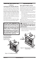
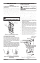
A manual shutoff valve has been included in the
applianceʼs gas supply system. You may consider
installing an extra gas shutoff valve outside the
applianceʼs enclosure (check with local codes)
where it can be accessed more conveniently with
a key through a wall as shown in Figure 18.
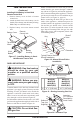
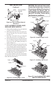
In conformance with local codes, route a 1/2" NPT
gas line to the appliance through hole in left side of
firebox or sub-floor as shown in Figure 19.
CAUTION: Do not kink flex-
ible gas line.
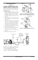
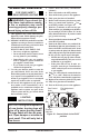
Installing 9-Volt Battery in Hand-Held
Remote Control Unit
1. Remove battery cover on back of remote
control unit.
2. Attach terminal wires to the battery (not in
-
cluded). Place battery into the battery housing.
Note: Only use alkaline battery.
3. Replace battery cover onto remote control
unit.
Figure 17 - Installing Battery in Hand-
Held Remote Control Unit
Battery Cover
9-Volt
Battery
Terminal
Wires
Remote
Control Unit
Battery
Housing
INSTALLATION
Continued
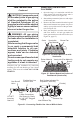
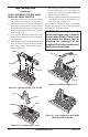
DESA recommends that a black iron gas line be
routed from the gas source, through a sediment
trap (shown in Figure 20) and into the appliance.
Once connected through the appliance, a flexible
gas line may be used for ease of installation to gas
control valve (see Figure 21, page 14).
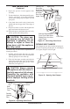
Before connecting the black iron gas line to the
inside of the appliance a sediment trap must be
included outside the appliance between the gas
line and the gas shutoff valve. It must extend
down three (3) inches beyond the center of the
pipe. Prepare incoming black iron gas line with
teflon tape or pipe joint compound (Check with
local building codes).
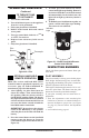
Figure 18 - Manual Shutoff Valve
Installation
Typical Exterior Wall Gas
Shutoff Installation
Key
Extension
Shutoff
Valve
Figure 19 - Routing Incoming Gas Line
A
1/2" NPT Incoming
Black Iron Gas Line
7"
7"
Alternate Gas Supply
Through Sub-Floor
M36(B,H),
M36P(B,H
VM36(B,H),
VM36P(B,H)
M42(B,H),
M42P(B,H)
VM42(B,H),
VM42P(B,H)
A 8
5
/
8
" (219 mm) 10
1
/
2
" (267 mm)
Incoming
1/2" Gas Line
Permitted by
Local Codes
Sediment
Trap (Not
Supplied)
Figure 20 - Sediment Trap
3" Min.
(76mm)