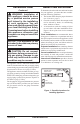
B-VENT DECORATIVE GAS FIREPLACE OWNER’S OPERATION AND INSTALLATION MANUAL MODELS M36(B,H), M42(B,H), VM36(B,H) AND VM42(B,H) NATURAL GAS MODELS M36P(B,H), M42P(B,H), VM36P(B,H) AND VM42P(B,H) PROPANE/LP GAS WARNING: If the information in these instructions is not followed exactly, a fire or explosion may result causing property damage, personal injury or death. FOR YOUR SAFETY — Do not store or use gasoline or any other flammable vapors or liquids in the vicinity of this or any other appliance.
WARNING: Improper installation, adjustment, alteration, service or maintenance can cause injury or property damage. Refer to this manual for correct installation and operational procedures. For assistance or additional information consult a qualified installer, service agency or the gas supplier. NOT FOR USE WITH SOLID FUEL CHECK LOCAL CODES PRIOR TO INSTALLATION SAVE THIS BOOK This book is valuable.
SAFETY INFORMATION WARNING: This product contains and/or generates chemicals known to the State of California to cause cancer or birth defects or other reproductive harm. IMPORTANT: Read this owner’s manual carefully and completely before trying to assemble, operate or service this fireplace. Improper use of this fireplace can cause serious injury or death from burns, fire, explosions, electrical shock and carbon monoxide poisoning.
SAFETY INFORMATION Continued 11. Keep the area around your fireplace clear of combustible materials, gasoline and other flammable vapor and liquids. Do not run fireplace where these are used or stored. Do not place items such as clothing or decorations on or around fireplace. 12. Do not use this fireplace to cook food or burn paper or other objects. 13. Do not use any solid fuels (wood, coal, paper, cardboard, etc.) in this fireplace. Use only the gas type indicated on fireplace nameplate. 14.
INTRODUCTION SELECTING LOCATION Continued To determine the safest and most efficient location for your appliance, you must take into consideration the following guidelines: 1. The location must allow for proper clearances (see Clearances, page 7). 2. Consider a location where heat output would not be affected by drafts, air conditioning ducts, windows or doors. 3. A location that avoids the cutting of joists or roof rafters will make installation easier.
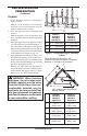
PRODUCT SPECIFICATIONS GAS RATING - NATURAL Max. Input Rating: Manifold Pressure: Minimum Supply Pressure: Maximum Supply Pressure: Orifice Size: M36(B,H), VM36(B,H) 40,000 Btu/Hr 3.5 in. WC (.87 kPa) 4.5 in. WC (1.12 kPa) 10.5 in. WC (2.66 kPa) # 30 M42(B,H), VM42(B,H) 45,000 Btu/Hr 3.5 in. WC (.87 kPa) 4.5 in. WC (1.12 kPa) 10.5 in. WC (2.66 kPa) # 29 GAS RATING - PROPANE/LP Max.
PRE-INSTALLATION PREPARATION MANTEL CLEARANCES AND WALL DETAILS CLEARANCES Minimum clearances to combustibles are: • Back and Sides of Outer Surround . . . 0" min. • Drywall to Sides of Front Face (Nailing Flanges) . . . . . . . . . . . . . . 0" min. • “B” Vent Surfaces . . . . . . . . . . . . . . . . 1" min. • Ceiling to Opening . . . . . . . . . . . . . . 42" min. • Floor . . . . . . . . . . . . . . . . . . . . . . . . . . 0" min. • Perpendicular Wall . . . . . . . . . . .
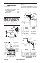
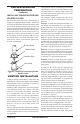
PRE-INSTALLATION PREPARATION Continued FRAMING 1. Frame appliance enclosure as illustrated in Figures 7 and 8. Note: If a wall covering is used to line the enclosure, then all measurements must be from the surface of the covering. 2. Place the appliance into the framing and secure it. Note: If appliance is to be raised above floor level, a platform must be built to support the appliance. 3.
PRE-INSTALLATION PREPARATION Continued INSTALLING TRANSITION PIPE AND STARTER COLLAR The transition pipe and starter collar shown in Figure 9 are supplied with the fireplace, unattached and ready for installation. Remove the starter collar and set aside. Slide the transition pipe over the vent collar and attach with a minimum of three screws. Replace the starter collar over the transition pipe and attach using four screws located on the leg stands (five used on the model M42).
VENTING INSTALLATION Continued Listed Vent Cap Maintain Listed Clearance Maintain Listed Clearance 12' Min. Position Firestop 45 6' Maintain Listed Clearance 12' Min. 45 12' Min.
INSTALLATION VENTING INSTALLATION Continued CHECKING FOR PROPER VENTING After completing and checking the electrical, gas and vent connections, follow the lighting instructions and allow the main burner to run for approximately 5 minutes. Hold a lighted match or cigarette near the top edge of the fireplace opening and play it along the entire length of the opening (see Figure 12). Proper venting should tend to draw the flame or smoke into the appliance.
INSTALLATION Receiver Continued OPTIONAL WIRELESS HAND-HELD REMOTE CONTROL INSTALLATION Note: If using optional wireless hand-held remote control, the wall switch is no longer operational. Installing Receiver 1. Remove the front refractory access panel by lifting up and angling out of the firebox opening (see Figure 13, page 11) to expose controls. 2. Disconnect wall switch wires from TH and TH/TP terminals on control valve (see Figure 14). 3.
INSTALLATION Continued Installing 9-Volt Battery in Hand-Held Remote Control Unit 1. Remove battery cover on back of remote control unit. 2. Attach terminal wires to the battery (not included). Place battery into the battery housing. Note: Only use alkaline battery. 3. Replace battery cover onto remote control unit. Remote Battery Cover Control Unit DESA recommends that a black iron gas line be routed from the gas source, through a sediment trap (shown in Figure 20) and into the appliance.
INSTALLATION EMBER AND PAN MATERIAL PLACEMENT Continued 1. Open the bag(s) of vermiculite and fill the entire burner pan until the burner tube is completely covered (see Figure 22). 2. Smooth the pan material just even with edges of the burner pan. 3. Remove the ember material from the bag and flatten small amounts into quarter size pieces and lay on top of the surface of the pan material (see Figure 23). 4.
INSTALLATION Continued Grate 0.5" Pan and Ember Material NOTICE: Do not put lava rock inside the burner pan or around the air mixer fitting. Placing lava rock inside the burner pan or blocking the openings of the propane/LP air-mixer could cause performance problems. Log 4 0.5" Burner Pan Figure 24 - Pan and Ember Material Clearances Log 3 Log 2 Notches LOG PLACEMENT FOR M36, M36P, VM36 AND VM36P MODELS 1. Place small front right log (log 1) on right front of grate as shown in Figure 25. 2.
INSTALLATION Continued LOG PLACEMENT FOR M42, M42P, VM42 AND VM42P MODELS 1. Place large back log (log 1) onto grate making sure notches rest over grate (see Figure 29). 2. Insert lower end of log 2A between the first two grate fingers and position the upper end into the notch on the front of log 1. See Figure 29. Place log 2B on the front right side of grate as shown in Figure 29. 3. Place log 3 into notch on top left of log 1, resting the lower end on the left two grate fingers (see Figure 30). 4.
INSTALLATION INSTALLING OPTIONAL GLASS DOOR ACCESSORY Continued COMBUSTION AIR KIT MODEL AK4 (OPTIONAL) The outside air kit may be installed on the left side of the fireplace only. The vent can be installed through any outside wall a minimum of three feet below fireplace termination cap. The handle to operate the damper door for the outside air inlet will be located inside the left “screen pocket” of the firebox (see Figure 33). Pull the handle to open or push to close.
INSTALLATION Continued 6. Repeat the process for the opposite door assembly. 7. To adjust the doors, slide them partially open. Using a screwdriver, loosen the hold-down screws in the spring clip (see Figure 36) and pivot plate. 8. Close both doors until evenly joined at the middle and note the gap at the outer edges of the face. 9. Reopen one door at a time and retighten the upper and lower hold-down screws. 10. Repeat the process until both doors are evenly joined, spaced and working freely.
OPERATING FIREPLACE FOR YOUR SAFETY READ BEFORE LIGHTING WARNING: If you do not follow these instructions exactly, a fire or explosion may result causing property damage, personal injury or loss of life. A. This appliance has a pilot which must be lighted by hand. When lighting the pilot, follow these instructions exactly. B. BEFORE LIGHTING smell all around the appliance area for gas. Be sure to smell next to the floor because some gas is heavier than air and will settle on the floor.
OPERATING FIREPLACE Continued TO TURN OFF GAS TO APPLIANCE 1. Turn off the wall switch. 2. Turn off all electric power to the appliance if service is to be performed. 3. Fully open glass doors if installed. 4. Remove front hearth brick and control access panel. 3. To Lock press both buttons on remote control until light stops flashing. Remote is now locked. If the fire is on it will be turned off automatically. In the locked state, the light will not light up when any button is pressed. 4.
INSPECTING BURNERS CLEANING AND MAINTENANCE Continued Thermopile Pilot Burner Ignitor Figure 42 - Correct Pilot Flame Pattern BURNER FLAME PATTERN Burner flames will be steady; not lifting or floating. Flames should go up through the middle of logset. Flames should not "spill" to the edges of the pan or sides of the logset. Figure 43 shows a typical flame pattern.
WIRING DIAGRAM PILOT BURNER THERMOPILE IGNITOR REPLACE FACTORY WIRING WITH 105°C EQUIVALENT OR HIGHER RATING EXTERNAL WIRING USE ONLY CLASS 2 THERMOSTAT WIRE 18 GA. RED/WHITE PILOT GAS LINE DO NOT CONNECT TO 120V RED WHITE N.O. SW N.C.
TROUBLESHOOTING Note: Before troubleshooting the system, make sure the gas shutoff valve is ON. The two most common causes of a malfunctioning gas appliance are: 1. Loose wiring connections 2. Construction debris clogging the pilot and/or gas control valve filter OBSERVED PROBLEM POSSIBLE CAUSE Pilot will not light 1. No gas supply or shutoff valve is OFF 2. Air in gas line 3. 4. 5. 6. 7. 8. Pilot will not stay lit REMEDY 1. Check to see if you have gas supply 2.
TROUBLESHOOTING Continued OBSERVED PROBLEM POSSIBLE CAUSE REMEDY Pilot goes out when wall switch is ON 1. Millivolt output on thermopile too high 1. Replace thermopile Spark ignitor will not light pilot after repeated triggering of red button 1. Defective ignitor (no spark at electrode) 1. Check for spark at the electrode and pilot; if no spark and electrode wire is properly connected, replace ignitor 2. Using a match, light pilot. If pilot lights, turn off pilot and trigger the red button again.
TROUBLESHOOTING Continued WARNING: If you smell gas • Shut off gas supply. • Do not try to light any appliance. • Do not touch any electrical switch; do not use any phone in your building. • Immediately call your gas supplier from a neighbor’s phone. Follow the gas supplier’s instructions. • If you cannot reach your gas supplier, call the fire department. IMPORTANT: Operating fireplace where impurities in air exist may create odors.
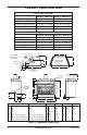
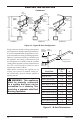
ILLUSTRATED PARTS BREAKDOWN MODELS M36(B,H), M36P(B,H), M42(B,H), M42P(B,H), VM36(B,H), VM36P(B,H), VM42(B,H) AND VM42P(B,H) 51 21 57 3 57 25 2 10 28 32 11 6 26 31 43 27 37 36 38 �� 35 34 30 33 18 24 11 63 34 35 �� 29 63 50 1 20 22 49 52 61 14 43 12 52 62 9 15 58 4 59/60 48 16 17 13 42 8 23 7 40 56 17 39 46 44 19 5 47 45 41 54 55 7 47 26 www.desatech.
PARTS LIST This list contains replaceable parts used in your heater. When ordering parts, follow the instructions listed under Replacement Parts on page 22 of this manual. KEY M36(B,H) M42(B,H) NO.
ILLUSTRATED PARTS BREAKDOWN BRICK LINERS FOR MODELS M36(B,H), M36P(B,H), VM36(B,H) AND VM36P(B,H) 14 12 16 13 15 KEY M36(B,H) M42(B,H) NO. VM36(B,H) VM42(B,H) DESCRIPTION 12 106658-02 107812-02 Left Refractory, Std. Brick (M36B/M42B) 108164-02 108169-02 Left Refractory, Herringbone (M36H/M42H) 106658-01 107812-01 Left Refractory, Std. Brick (VM36B/VM42B) 108164-01 108169-01 Left Refractory, Herringbone (VM36H/VM42H) 13 106659-02 107814-02 Right Refractory, Std.
ILLUSTRATED PARTS BREAKDOWN LOGSETS FOR MODELS M36(B,H), M36P(B,H), VM36(B,H) AND VM36P(B,H) 5 4 6 3 5 4 2 3 1 KEY NO. PART NUMBER DESCRIPTION - 107999-01 Log Set 1 108724-01 Right Front 9" Split Log 1 2 901098-01 Rear Log 1 3 QTY. 108720-01 3 Top Right Log - 11 /4" 1 4 108721-01 Top Right Log - 16" 1 5 108722-01 Top Left Log - 13 1/2" Y-Log 1 6 108723-01 Top Left Log - 11" 1 1 2A 2B 108795-01N www.desatech.
5 ILLUSTRATED PARTS BREAKDOWN 4 FOR LOGSETS MODELS M42(B,H), M42P(B,H), VM42(B,H) AND VM42P(B,H) 3 5 4 3 1 6 1 2A 2B 30 KEY PART NO. NUMBER DESCRIPTION - 107999-02 Log Set 1 901098-02 Rear Log 1 2A 108723-01 Left Front Log - 11" 1 2B 108839-01 Right Front Log - 15 3/4" Round 1 3 108722-01 Top Left Log - 13 /2" Y-Log 1 4 108838-01 Inside Top Left Log - 15 /4" Split 1 5 108721-01 Inside Top Right Log - 16" 1 6 108720-01 Top Right Log - 11 /4" 1 QTY. 1 3 3 www.
ACCESSORIES NOTICE: All accessories may not be available for all fireplace models. Purchase these firebox accessories from your local dealer. If they can not supply these accessories, call DESAʼs Sales Department at 1-866-672-6040 for information. You can also write to the address listed on the back page of this manual. AIR KIT - AK4 BLOWER KIT Optional kit helps offset the negative pressure often existing in today's tightly constructed homes.
WARRANTY INFORMATION KEEP THIS WARRANTY Model Serial No. Date Purchased Always specify model and serial numbers when communicating with the factory. We reserve the right to amend these specifications at any time without notice. The only warranty applicable is our standard written warranty. We make no other warranty, expressed or implied.