UNVENTED (VENT-FREE) GAS COMPACT CLASSIC HEARTH® DUAL BURNER FIREPLACE OWNER’S OPERATION AND INSTALLATION MANUAL For more information, visit www.desatech.com Thermostat Models: CDCFTN, CDCFTP, VDCFTN, VDCFTP, FDCFTN, FDCFTP Remote-Ready Models: VDCFRN, VDCFRP, FDCFRN, FDCFRP Shown with Optional Cabinet Mantel/Hearth Base Accessory WARNING: If the information in this manual is not followed exactly, a fire or explosion may result causing property damage, personal injury, or loss of life.
TABLE OF CONTENTS SAFETY INFORMATION TABLE OF CONTENTS SAFETY INFORMATION ............................................................ 2 CLEANING AND MAINTENANCE ............................................ 24 PRODUCT IDENTIFICATION ..................................................... 3 WIRING DIAGRAM ................................................................... 25 OPTIONAL REMOTE CONTROL ACCESSORIES .................... 4 TROUBLESHOOTING .....................................................
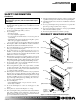
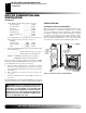
SAFETY INFORMATION PRODUCT IDENTIFICATION 3 3 SAFETY INFORMATION Continued 5. 6. 7. 8. 9. 10. 11. 12. Hood Screen Log Ignitor Button Control Knob Fireplace Cabinet Hood Logs Ignitor Button L P Control Knob Figure 1 - Vent-Free Compact Dual Flame Fireplace For more information, visit www.desatech.com 111244-01A O FF Remote Control (Optional) O 13. 14. Fireplace Cabinet I 4. PRODUCT IDENTIFICATION H 3. N 2.
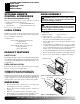
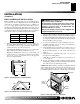
OPTIONAL REMOTE CONTROL ACCESSORIES LOCAL CODES PRODUCT FEATURES UNPACKING HOOD ASSEMBLY OPTIONAL REMOTE CONTROL ACCESSORIES (For Remote-Ready Models Only) There are four optional remote controls that can be purchased separately for Remote-Ready Models only: • wall switch • hand-held ON/OFF remote • wall thermostat • hand-held thermostat remote See Accessories, pages 36 and 37. LOCAL CODES Install and use fireplace with care. Follow all local codes.
AIR FOR COMBUSTION AND VENTILATION Providing Adequate Ventilation Determining Fresh-Air Flow for Fireplace Location 5 5 AIR FOR COMBUSTION AND VENTILATION WARNING: This fireplace shall not be installed in a confined space or unusually tight construction unless provisions are provided for adequate combustion and ventilation air. Read the following instructions to insure proper fresh air for this and other fuel-burning appliances in your home. c.
AIR FOR COMBUSTION AND VENTILATION Determining Fresh-Air Flow for Fireplace Location (Cont.) Ventilation Air AIR FOR COMBUSTION AND VENTILATION Continued 3. Add the Btu/Hr of all fuel burning appliances in the space.
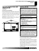
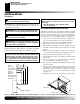
AIR FOR COMBUSTION AND VENTILATION INSTALLATION Ventilation Air (Cont.) INstallation AIR FOR COMBUSTION AND VENTILATION Continued Ventilation Air From Outdoors Provide extra fresh air by using ventilation grills or ducts. You must provide two permanent openings: one within 12" of the ceiling and one within 12" of the floor. Connect these items directly to the outdoors or spaces open to the outdoors. These spaces include attics and crawl spaces. Follow the National Fuel Gas Code, ANSI Z223.
INSTALLATION Check Gas Type Installation Items Fireplace Clearances INSTALLATION Continued Use the dimensions shown for rough openings to create the easiest installation (see Built-In Fireplace Installation, page 9). CHECK GAS TYPE Use the correct gas type (natural or propane/LP) for your unit. If your gas supply is not correct, do not install fireplace. Call dealer where you bought fireplace for proper type fireplace.
INSTALLATION Built-In Fireplace Installation 9 9 INSTALLATION Continued BUILT-IN FIREPLACE INSTALLATION WARNING: If pre-wiring, do not connect wiring to any electrical source at this time. Install fireplace electrical outlet and connect wiring to outlet before connecting to electrical source. The fireplace electrical outlet is included with the GA3450TA blower accessory. Only use the fireplace electrical outlet supplied with the GA3450TA blower accessory.
INSTALLATION 10 Built-In Fireplace Installation (Cont.) Optional Mantel Installation INSTALLATION Continued WARNING: Do not allow any combustible materials to overlap the firebox front facing. IMPORTANT: Noncombustible materials such as brick, tile, etc. may overlap the front facing, but should never cover any necessary openings like louvered slots.
INSTALLATION Optional Mantel Installation (Cont.) Installing Optioanl Blower Accessory GA3450TA 11 11 INSTALLATION Continued 13. Check for leaks. See Checking Gas Connections, page 16. 14. Place mantel around fireplace. Be careful not to damage wall or mantel. 15. Place perimeter trim kit on the shoulder screws located on the side and top of the fireplace. Firmly snap trim over shoulder screws on fireplace (see Figure 12). 16. Adjust assembly to remove any gaps.
INSTALLATION 12 Installing Optional Blower Accessory GA3450TA (Cont.) INSTALLATION Continued Installing Blower Accessory 5. CAUTION: Label all wires prior to disconnection when servicing controls. Wiring errors can cause improper and dangerous operation. CAUTION: Verify proper operation after servicing. Note: If you are using a mantel with your fireplace, use the following instructions. If your fireplace is built-in, see For Built-In Installation, page 13. 1.
INSTALLATION Installing Blower Accessory GA3450TA (Cont.) 13 13 INSTALLATION Continued For Built-In Installation Fan Switch (Auto/Off/On) Auto 1 WARNING: A licensed electrician must connect the wiring harness to electrical supply following all local codes. Electrician must provide a clamp on the box cover to secure the wiring. Wiring should be routed through the bushing in the hole on the outer casing of fireplace. 1. 2. 3. 4. 5. 6.
INSTALLATION Connecting to Gas Supply INSTALLATION Continued CONNECTING TO GAS SUPPLY WARNING: This appliance requires a 45° male flare fitting 5/8"-18 UNF (Unified National Fine Thread) inlet connection and the flexible gas line provided. WARNING: A qualified service person must connect fireplace to gas supply. Follow all local codes. WARNING: Never connect natural gas fireplace to private (non-utility) gas wells. This gas is commonly known as wellhead gas.
INSTALLATION Connecting To Gas Supply (Cont.) Connecting Equipment Shutoff Valve To Heater Control 15 15 INSTALLATION Continued We recommend that you install a sediment trap in supply line as shown in Figure 20, page 14. Locate sediment trap where it is within reach for cleaning. Install in piping system between fuel supply and heater. Locate sediment trap where trapped matter is not likely to freeze. A sediment trap traps moisture and contaminants. This keeps them from going into fireplace controls.
INSTALLATION Checking Gas Connections INSTALLATION Continued CHECKING GAS CONNECTIONS WARNING: Test all gas piping and connections, internal and external to unit, for leaks after installing or servicing. Correct all leaks at once. 3. 4. Check all joints from gas meter to equipment shutoff valve for natural gas or propane/LP supply to equipment shutoff valve for propane/LP (see Figures 24 or 25). Apply noncorrosive leak detection fluid to all joints. Bubbles forming show a leak.
INSTALLATION Optional Wireless Hand-Held Remote Control Accessories [Remote-Ready Models Only] 17 17 INSTALLATION Continued OPTIONAL WIRELESS HAND-HELD REMOTE CONTROL ACCESSORIES Remote-Ready Models Only ([C]GHRCB Series & [C]GHRCTB Series) Installing Receiver 1. 2. 3. 4. 5. 6. Disconnect wires from the control valve (see Figure 26) . Locate the battery clip mounted on the back of the receiver (see Figure 27). Slide 9-volt battery (not included) through the clip.
INSTALLATION Optional Wall Mounted Thermostat - GWMT1 (Remote-Ready Models Only) Optional Wall Switch - GWMS2 (Remote-Ready Models Only) INSTALLATION Continued OPTIONAL WALL MOUNTED THERMOSTAT GWMT1 (Remote-Ready Models Only) WARNING: Read and follow installation instructions. Installation should be done by a qualified installer familiar with low-voltage wiring procedures. 7. 8. Install the base onto the wall with the provided screws.
INSTALLATION Installing Log Set and Screen OPERATING FIREPLACE (THERMOSTAT-CONTROLLED MODELS) 19 19 For Your Safety Read Before Lighting Lighting Instructions INSTALLATION Continued INSTALLING LOG SET AND SCREEN 1. 2. Remove log packaging material and discard packaging. Gently place log over burner (see Figure 34). Do not allow log to contact flame. If flame contacts log, soot will be created. Reattach screen by placing the notches in the screen frame over the shoulder screws and pushing down.
OPERATING FIREPLACE (THERMOSTAT-CONTROLLED MODELS) Lighting Instructions (Cont.) To Turn Gas Off To Appliance Thermostat Control Operation Manual Lighting Procedure Operating Blower OPERATING FIREPLACE Continued 6. 7. 8. With control knob pressed in, press and release ignitor button. This will light pilot. The pilot is attached to the front burner. If needed, keep pressing ignitor button until pilot lights. Note: If pilot does not stay lit, refer to Troubleshooting, pages 26 through 28.
OPERATING FIREPLACE (REMOTE-READY MODELS) 21 21 For Your Safety Read Before Lighting Lighting Instructions OPERATING FIREPLACE Continued REMOTE-READY MODELS FOR YOUR SAFETY READ BEFORE LIGHTING WARNING: If you do not follow these instructions exactly, a fire or explosion may result causing property damage, personal injury or loss of life. A. This appliance has a pilot which must be lighted by hand. When lighting the pilot, follow these instructions exactly. B.
OPERATING FIREPLACE (REMOTE-READY MODELS) To Turn Off Gas To Appliance Manual Lighting Procedure Optional Hand-held Remote Operation OPERATING FIREPLACE Continued Selector Switch in Remote Position (Optional Remote Control) TO TURN OFF GAS TO APPLIANCE Flame Adjustment Knob Control Knob OUT Shutting Off Fireplace 1. 2. Shutting Off Burners Only (pilot stays lit) You may shut off the burners and keep the pilot lit by doing one of the following: 1. Turn control knob clockwise to the PILOT position.
OPERATING FIREPLACE (REMOTE-READY MODELS) Optional Hand-Held Remote Operation (Cont.) Optional GWMT1 Wall Mounted Thermostat Optional GWMS2 Wall Mounted Switch Operating Blower 23 23 OPERATING FIREPLACE Continued Note: Do not leave the hand-held remote in the AUTO mode close to the fireplace. The radiant heat from the fireplace will turn off the fireplace. Ideally, place the hand-held remote in the center of the room facing towards the fireplace. Note: Do not hold the hand-held remote for a long time.
INSPECTING BURNERS Pilot Flame Pattern Burner Flame Pattern CLEANING AND MAINTENANCE Cleaning Burner Injector Holder and Pilot Air Inlet Hole INSPECTING BURNERS Check pilot flame pattern and burner flame patterns often. PILOT FLAME PATTERN Figure 46 shows a correct pilot flame pattern. Figure 47 shows an incorrect pilot flame pattern. The incorrect pilot flame is not touching the thermocouple. This will cause the thermocouple to cool. When the thermocouple cools, the fireplace will shut down.
CLEANING AND MAINTENANCE Cleaning Burner Injector Holder and Pilot Air Inlet Hole (Cont.) Log Set Cabinet 25 25 WIRING DIAGRAM CLEANING AND MAINTENANCE WIRING DIAGRAM (Remote-Ready Models Only) Continued 5. 6. Blow air into the primary air holes on the injector holder. In case any large clumps of dust have now been pushed into the burner repeat steps 3 and 4. Clean the pilot assembly also. A yellow tip on the pilot flame indicates dust and dirt in the pilot assembly.
TROUBLESHOOTING TROUBLESHOOTING Note: For additional help, visit DESA Heating Products’ technical service web site at www.desatech.com. Note: All troubleshooting items are listed in order of operation. WARNING: Turn off and unplug fireplace and let cool before servicing. Only a qualified service person should service and repair fireplace. CAUTION: Never use a wire, needle, or similar object to clean ODS/pilot. This can damage ODS/pilot unit.
TROUBLESHOOTING 27 27 TROUBLESHOOTING Continued OBSERVED PROBLEM POSSIBLE CAUSE REMEDY Burner does not light after ODS/pilot is lit 1. Inlet gas pressure is too low 1. Contact local natural or propane/LP gas company 2. Clean burner (see Cleaning and Maintenance, pages 24 and 25) or replace burner orifice 3. Reconnect leads (see Wiring Diagram, page 25) 2. Burner orifice is clogged 3. Thermopile leads disconnected or improperly connected (Remote-Ready Models Only) 4.
TROUBLESHOOTING TROUBLESHOOTING Continued WARNING: If you smell gas • Shut off gas supply. • Do not try to light any appliance. • Do not touch any electrical switch; do not use any phone in your building. • Immediately call your gas supplier from a neighbor’s phone. Follow the gas supplier’s instructions. • If you cannot reach your gas supplier, call the fire department. IMPORTANT: Operating fireplace where impurities in air exist may create odors.
SPECIFICATIONS SERVICE HINTS TECHNICAL SERVICE REPLACEMENT PARTS 29 29 SPECIFICATIONS Thermostat Models: CDCFTP, VDCFTP, FDCFTP Thermostat Models: CDCFTN, VDCFTN, FDCFTN Remote-Ready Models: VDCFRP, FDCFRP Remote-Ready Models: VDCFRN, FDCFRN Btu/Hr 17/26,000 17/26,000 17/26,000 17/26,000 Type Gas Propane/LP Gas Only Natural Gas Only Propane/LP Gas Only Natural Gas Only Ignition Piezo Piezo Piezo Piezo Manifold Pressure 8" W.C. 3.5" W.C. 8" W.C. 3.5" W.C. Inlet Gas Pressure (in.
ILLUSTRATED PARTS BREAKDOWN Firebox ILLUSTRATED PARTS BREAKDOWN FIREBOX 19 16 16 19 4 1 2 8 5 6 16 16 10 10 16 16 9 10 19 10 10 19 16 16 8 19 17 16 11 18 15 16 16 19 13 3 9 12 19 11 7 16 14 For more information, visit www.desatech.
PARTS LIST Firebox PARTS LIST FIREBOX This list contains replaceable parts used in your fireplace. When ordering parts, follow the instructions listed under Replacement Parts on page 29 of this manual. KEY PART NUMBERS NO.
ILLUSTRATED PARTS BREAKDOWN MODELS FDCFTP, FDCFTN, VDCFTP, VDCFTN, CDCFTP and CDCFTN ILLUSTRATED PARTS BREAKDOWN THERMOSTAT MODELS FDCFTP, FDCFTN, VDCFTP, VDCFTN, CDCFTP and CDCFTN 9 4 2 1 3 6 5 7 9 8 10 21 9 17 12 11 14 16 13 6 20 VDCF Logs Shown 15 19 18 For more information, visit www.desatech.
PARTS LIST 33 33 MODELS FDCFTP, FDCFTN, VDCFTP, VDCFTN, CDCFTP and CDCFTN PARTS LIST THERMOSTAT MODELS This list contains replaceable parts used in your fireplace. When ordering parts, follow the instructions listed under Replacement Parts on page 29 of this manual. KEY NO.
ILLUSTRATED PARTS BREAKDOWN Models FDCFRN, FDCFRP, VDCFRN and VDCFRP ILLUSTRATED PARTS BREAKDOWN REMOTE-READY MODELS FDCFRN, FDCFRP, VDCFRN and VDCFRP 4 9 2 1 3 6 7 8 5 9 10 9 11 12 14 12 20 21 Natural Gas Only 22 15 9 16 16 H I 15 L O N O FF O P ILOT VDCF Logs Shown 19 18 17 13 For more information, visit www.desatech.
PARTS LIST Models FDCFRN, FDCFRP, VDCFRN and VDCFRP PARTS LIST REMOTE-READY MODELS This list contains replaceable parts used in your fireplace. When ordering parts, follow the instructions listed under Replacement Parts on page 29 of this manual. KEY NO.
ACCESSORIES 36 ACCESSORIES NOTICE: All accessories may not be available for all fireplace models. Purchase these fireplace accessories from your local dealer. If they can not supply these accessories, call DESA Heating Products at 1-866-672-6040 for referral information. You can also write to the address listed on the back page of this manual. CABINET MANTEL WITH BASE EQUIPMENT SHUTOFF VALVE - GA5010 For all models. Equipment shutoff valve with 1/8" NPT tap. Fits 1/2" NPT pipe.
ACCESSORIES 37 37 ACCESSORIES Continued RECEIVER AND HAND-HELD THERMOSTAT REMOTE CONTROL KIT - GHRCTB AND CGHRCTB For all remote-ready models. Allows the fireplace to be operated in a manually or thermostatically controlled mode. You can turn the fireplace on and off without ever leaving the comfort of your easy chair.
NOTES NOTES _______________________________________________________________________________________________ _______________________________________________________________________________________________ _______________________________________________________________________________________________ _______________________________________________________________________________________________ _______________________________________________________________________________________________ _______________
39 OWNER'S REGISTRATION FORM • ACCESSORIES In order to provide better customer service for this and future purchases, we recommend that you register your product with us. You can register online at www.desatech.com. If access to our website is not available to you, please complete this Owner’s Registration Form and mail to the address on the back of this owner’s manual. Please provide the following product information: Brand: (Comfort Glow, Vanguard, etc.) Model: (EFP33PR, VTGH33NR, etc.
TAPE 40 Postage Required 2701 Industrial Drive P.O. Box 90004 Bowling Green, KY 42102-9004 For more information, visit www.desatech.
NOTES 41 41 NOTES _______________________________________________________________________________________________ _______________________________________________________________________________________________ _______________________________________________________________________________________________ _______________________________________________________________________________________________ _______________________________________________________________________________________________ ____________
2701 Industrial Drive P.O. Box 90004 Bowling Green, KY 42102-9004 www.desatech.com 111244 01 NOT A UPC 111244-01 Rev. A 04/03 For more information, visit www.desatech.