
DIRECT-VENT FIREPLACE OWNER'S OPERATION AND INSTALLATION MANUAL (V)T36NA, (V)T36PA


www.desatech.com
111250-01E28
OPERATING FIREPLACE
Continued
MANUAL LIGHTING
PROCEDURE
1. Removeglassdoor(seeRemoving/Replacing
Glass Door,page24.)
2. Follow steps 1 through 7 under Lighting
Instructions, page27.
3. Depress gas control knob and light pilot
withmatch.
4. Keep gas control knob pressed in for 30
seconds after lighting pilot.After30 sec-
onds,releasegascontrolknob.Followsteps
9through12underLighting Instructions,
page27.
5. Replaceglassdoor(seeRemoving/Replacing
Glass Door, page24).
OPTIONAL HAND-HELD
REMOTE OPERATION
Note:Allremotecontrolaccessoriesmustbe
purchased separately (see Accessories, page
36). Follow instructions included with the
remotecontrol.
-
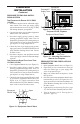
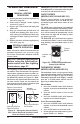
Lighting
Instructions
Afterlighting, let pilot ame burn for about
oneminute.TurncontrolknobtoONposition.
Adjust ame adjustment knob anywherebe-
tweenHIandLO.Slidetheselectorswitchto
theREMOTEposition(seeFigure51).Note:
Theburnermaylightifhand-heldremotewas
on when selector switch was last turned off.
Youcannowturntheburneronandoffwith
thehand-heldremotecontrolunit.
IMPORTANT:Donotleavetheselectorswitch
intheREMOTEorONpositionwhenthepilot
is not lit. This will drain the battery.
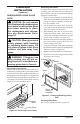
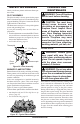
ON/OFF SERIES
Hold the control button on the hand-held
remote until burner turns on. Hold the con-
trol button again until burner turns off (see
Figure52).
press both buttons on hand-held
remotecontroluntillightstopsashing.Hand-
heldremotecontrolisnowlocked.Ifthereis
on it will be turned off automatically. In the
locked state, the light will not light up when
anybuttonispressed.
press both buttons together
on hand-held remote control until the light
stops ashing. The hand-held remote is now
unlocked.
O
F
F
P
I
L
O
T
L
O
I
H
ON
OFF
REMOTE
ON
OFF
O
N
Selector Switch in
Remote Position
Figure 51 - Setting the Selector Switch,
Gas Control Knob and Variable Contorl
Knob for Remote Operation
Blower Control Knob
(Optional Accessory)
Gas Control Knob in
ON Position
Variable
Control Knob
Figure 52 - On/Off Hand-Held Remote
Control Unit HRC100
Control
Button
Indicator
Light
THERMOSTAT SERIES
Thehand-heldremotecan be operatedusing
eitherthemanualmode(MANU)orthermostatic
mode(AUTO)(seeFigure53,page29).Toselect
Fahrenheit/Centigrademodedisplay,carefully
pressthe˚C/˚Fmodebuttonwiththe end ofa
papercliporsimilarbluntobject.
Manual Mode
1. Press the POWER and LOCK buttons
togethertoturnonthehand-heldremote
control.
2. Press the MANU button to turn on the
replace.
3. Press the POWER and LOCK buttons
togethertoturnoffthereplace.
1. Press the POWER and LOCK buttons
togethertoturnonthehand-heldremote
control.
2. PressAUTObuttontoselectthismode.
3. Setthedesiredroomtemperaturebypress-
ingtheTEMP+or-buttons.