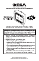
DIRECT-VENT Fireplace OWNER’S OPERATION AND INSTALLATION MANUAL NATURAL GAS “TUDOR” MODELS (V)T32EN-A SERIES PROPANE/LP GAS “TUDOR” MODELS (V)T32EP-A SERIES WARNING: If the information in this manual is not followed exactly, a fire or explosion may result causing property damage, personal injury or loss of life. — Do not store or use gasoline or other flammable vapors and liquids in the vicinity of this or any other appliance. — WHAT TO DO IF YOU SMELL GAS • Do not try to light any appliance.
WARNING: Improper installation, adjustment, alteration, service or maintenance can cause injury or property damage. Refer to this manual for correct installation and operational procedures. For assistance or additional information consult a qualified installer, service agency or the gas supplier. This appliance may be installed in an aftermarket,* permanently located, manufactured (mobile) home, where not prohibited by local codes.
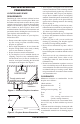
SAFETY INFORMATION Continued DANGER: Carbon monoxide poisoning may lead to death! This fireplace must be installed by a qualified (certified or licensed) service person. It has a sealed gas combustion chamber that uses a coaxial pipe (pipe within a pipe and having the same center) venting system. It brings in fresh air for combustion through the outer pipe and combustion gases are exhausted through the inner pipe.
SAFETY INFORMATION Continued 6. Turn fireplace off and let cool before servicing, installing or repairing. Only a qualified service person should install, service or repair this fireplace. Have fireplace inspected annually by a qualified service person. 7. You must keep control compartments, burners and circulating air passages clean. More frequent cleaning may be needed due to excessive lint and dust from carpeting, bedding material, etc. Turn off the gas valve and pilot light before cleaning fireplace. 8.
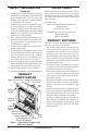
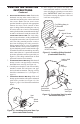
Pre-Installation Preparation Location and space requirements Determine the safest and most efficient location for your DESA direct-vent fireplace. Make sure that rafters and wall studs are not in the way of the venting system. Choose a location where the heat output is not affected by drafts, air conditioning ducts, windows or doors. Figure 2 shows some common locations. Be aware of all restrictions and precautions before deciding the exact location for your fireplace and termination cap.
Pre-Installation Preparation Continued NOTICE: This fireplace is intended for use as supplemental heat. Use this fireplace along with your primary heating system. Do not install this fireplace as your primary heat source. If you have a central heating system, you may run system’s circulating blower while using fireplace. This will help circulate the heat throughout the house. In the event of a power outage, you can use this fireplace as a heat source.
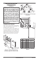
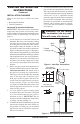
Location of Termination Cap N N D H V L E B C Fixed Closed F B Openable Fixed Closed V Openable V I V G B V B B J X V G G M A V K X V A G GAS METER RESTRICTED AREA V TERMINATION CAP X AIR SUPPLY INLET (TERMINATION PROHIBITED) A = clearance above grade, veranda, porch, deck, or balcony I = clearance to service regulator vent outlet [*72 inches (182.9cm) [*12 inches (30.
Venting Installation Instructions NOTICE: Failure to follow these instructions will void the warranty. NOTICE: Read these instructions completely before attempting installation. Important: Do not seal vent cap to pipe. Cap must be removable for service. These models are tested and approved for use with DESA (direct-vent) pipe components and terminations.
Venting Installation instructions Continued INSTALLATION PLANNING There are two basic types of direct-vent installation: • Horizontal Termination • Vertical Termination Horizontal Termination Installation IMPORTANT: Horizontal square terminations require only inner portion of wall firestop. Horizontal installations using round termination require exterior portion of wall firestop (see Figure 14, page 11). 1.
Venting Installation instructions Continued 6. Noncombustible Exterior Wall: Position the horizontal vent cap in the center of the 8 1/2" round hole and attach to the exterior wall with four screws. Note: The four wood screws provided should be replaced with appropriate fasteners for stucco, brick, concrete or other types of sidings. Before attaching the vent cap to exterior wall, run a bead of non-hardening mastic (pliable sealant) around the outside edges to make a seal between it and the outside wall.
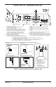
Venting Installation instructions Continued Siding Standoff Minimum Pipe Overlap 11/4" Screws GROUND FLOOR INSTALLATION Recommended Applications: • Installation using cabinet surrounds • Through the wall using round or square termination (up to 12" horizontal pipe) • NOT FOR CORNER INSTALLATION 45° Elbow Horizontal High Wind Square Termination Wall Firestop Adjustable Pipe 12" Wall Max.
Venting Installation instructions Continued CORNER INSTALLATION Recommended Applications: • Corner ground floor installation • Ground floor installation where pipe vents horizontally through wall (over 12" horizontal pipe) • Basement installation where one foot clearance from ground to termination is possible Not to Exceed 90° Elbow Not to Exceed Square (H) Limits (H) Limits Termination Square As Required 90° Termination for (V), See Elbow Chart for Pipe Section Required Wall Firestop Wall Firestop 45° Elb
Venting Installation instructions Continued HORIZONTAL SYSTEM INSTALLATION USING TWO 90° ELBOWS The following configurations show the minimum vertical rise requirements for a horizontal system using two 90° elbows. Venting with Two 90° Elbows Horizontal (H1) + Vertical (V) Horizontal (H1) Horizontal (H2) 5' min. 2' max. 6' max. 6' min. 4' max. 12' max. 7' min. 6' max. 18' max. 8' min. 8' max. 20' max. 20' max. 8' max. 20' max.
Venting Installation instructions Continued installation for vertical termination Note: Vertical restrictor must be installed in all vertical installations. 1. Determine the route your vertical venting will take. If ceiling joists, roof rafters or other framing will obstruct the venting system, consider an offset (see Figure 19) to avoid cutting load bearing members.
Venting Installation instructions Venting with One 90° Elbow Vertical (V) Horizontal (H) 5' min. 2' max. 6' min. 4' max. 7' min. 6' max. 8' min. 8' max. 20' max. 8' max. 45° Elbow Continued 6. Continue to add pipe sections until the height of the vent cap meets the minimum building code requirements described in Figure 7 on page 7. Note: You must increase vent height for steep roof pitches.
Venting Installation instructions Continued When installing this fireplace at an elevation above 4500 feet (in Canada), check with local authorities. Consult your local gas company to help determine the proper orifice for your location. For assistance with any high altitude installation contact DESA’s Customer Service Department at 1-866-672-6040. parts list for venting kits and components Vertical Venting V = 40' max. Note: Install restrictor into inner collar of fireplace as shown.
Venting Installation instructions Continued Number HHTK-58 Description High Wind Round Horizontal Termination Kit (Includes Round Termination, Wall Firestop, 45° Elbow) HHT-58 High Wind Round Termination Kit, Galvinized HTK-58 Horizontal Round Termination Kit (Includes Round Termination, Wall Firestop, 45° Elbow) HT-58 Horizontal Round Termination, Galvanized HTS-58 Horizontal Square Termination, Galvanized HTKS-58 Horizontal Square Termination Kit (Includes: Square Termination, Wall Firestop, 45° Elbow) H
Fireplace Installation Switch Bracket Continued al ffO kc kc B B al kc W ih et al B 1 01 1/ .V 51 .A .C B al kc hW i et erG ne 18 nO 9. Check to make sure that the power cord is completely clear of the blower wheel and that there are no other foreign objects in blower wheel. Turn blower on and check for operation. Turn blower off by turning knob fully counterclockwise before continuing. 10.
Fireplace Installation Continued 3. Place the blower against the lower rear wall of the firebox outer wrapper with the exhaust port directed upward and the thermodisc positioned up near the fireplace bottom. The thermodisc must be oriented near the fireplace bottom as shown in Figure 28, in order to sense temperature and properly operate. The blower will be held in position against the back wall by the magnets incorporated onto the blower housing (see Figure 28). 4.
Fireplace Installation Continued Installing Gas Piping to Fireplace Location WARNING: A qualified service person must connect fireplace to gas supply. Follow all local codes. CAUTION: For propane/LP units, never connect fireplace directly to the propane/LP supply. This heater requires an external regulator (not supplied). Install the external regulator between the fireplace and propane/LP supply. Installation Items Needed Before installing fireplace, make sure you have the items listed below.
Fireplace Installation Continued IMPORTANT: Install main gas valve (equipment shutoff valve) in an accessible location. The main gas valve is for turning on or shutting off the gas to the appliance. Check your building codes for any special requirements for locating equipment shutoff valve to fireplaces. Apply pipe joint sealant lightly to male NPT threads. This will prevent excess sealant from going into pipe. Excess sealant in pipe could result in clogged fireplace valves.
Fireplace Installation Continued Test Pressures Equal To or Less Than 1/2 PSIG (3.5 kPa) 1. Close equipment shutoff valve (see Figure 33). 2. Pressurize supply piping system by either opening propane/LP supply tank valve for propane/LP gas fireplace or opening main gas valve located on or near gas meter for natural gas fireplace or using compressed air. 3. Check all joints from propane/LP supply tank for propane/LP or gas meter for natural gas to equipment shutoff valve (see Figure 34 or Figure 35).
6. Replace screen/rod assembly by reversing step 1. 7. Replace louvers by reversing procedure under Removing Louver Panels, page 22 Fireplace Installation Continued Cleaning Glass Door See Cleaning and Maintenance on page 28. Installing Optional Brick liner Model BL32D Spring Latch Louver Panel Figure 36 - Removing Louver Panel Removing Glass Door If replacement of glass is necessary, the entire assembly, glass and frame, must be replaced.
Fireplace Installation Continued 6. Install left side brick panel by sliding it between the grate and the side of the firebox (see Figure 39). 7. Install the right brick panel using the same method described 8. Replace deflector shield using screws removed in step 4, page 23. 9. Follow instructions beginning in column 2 to install logs, lava rock and ember material. 10. Close glass door, lock latches on top and bottom of door and replace screen (see steps 5 and 6 of Removing Glass Door, page 23). 11.
Fireplace Installation WALL SWITCH INSTALLATION Continued 8. Pull ember material apart into pieces no larger than a dime. Place these pieces loosely and sparingly directly onto the exposed section of the front burner and along the space between the burner and grate prongs (see Figure 45). This will create the glowing ember appearance as the flame touches the ember material. Do not block air slots by using too much ember material in one area. It is not necessary to use all of the ember material provided.
Wiring Diagram PILOT IGNITOR LEAD ORANGE BLUE E8 E6 E4 E3 E2 WHITE 120V AC EV1 TRANSFORMER 24V AC SYNETEK CONTROLS INC IS1070B E12 BLACK GROUND EV2 RED GREEN Operating Fireplace FOR YOUR SAFETY READ BEFORE LIGHTING WARNING: If you do not follow these instructions exactly, a fire or explosion may result causing property damage, personal injury or loss of life. A. This appliance is equipped with an ignition device which automatically lights the pilot. Do not try to light the pilot by hand. B.
OPERATIng fireplace Continued 7. Turn equipment shutoff valve counterclockwise to the ON position. Do not force. 8. Close lower louver panel. 9. Turn on all electric power to the appliance. 10. Turn the wall switch to the ON position. 11. Visually locate the pilot. The ignitor should begin to spark and the main burner should ignite once flame appears at pilot. • If lighting the appliance for the first time each season, it may take several attempts before the supply gas can reach the pilot and main burners.
Inspecting Burners Check pilot flame pattern and burner flame patterns often. PILOT Assembly The pilot assembly is factory preset for the proper flame. Alterations may have occurred during shipping and handling. The pilot is located on the left hand side of the burner. The flame must envelope 1/4" of top of the ignitor/ sensor and grounding stem.
Cleaning and Maintenance Continued WARNING: Only parts supplied by the manufacturer should be used when replacing broken or damaged glass door panel (see Replacement Parts, page 32). This glass door panel is a complete unit. No substitute materials may be used. CAUTION: Wear gloves and safety glasses while handling or removing broken glass. Do not remove if glass is hot. Keep children and pets away from glass.
Troubleshooting WARNING: Turn off heater and let cool before servicing. Only a qualified service person should service and repair heater. CAUTION: Never use a wire, needle or similar object to clean pilot. This can damage pilot unit. Note: Before troubleshooting the system, make sure the gas shutoff valve is ON. The two most common causes of a malfunctioning gas appliance are: 1. Loose wiring connections 2.
TROUBLESHOOTING Continued WARNING: If you smell gas • Shut off gas supply. • Do not try to light any appliance. • Do not touch any electrical switch; do not use any phone in your building. • Immediately call your gas supplier from a neighbor’s phone. Follow the gas supplier’s instructions. • If you cannot reach your gas supplier, call the fire department. OBSERVED PROBLEM POSSIBLE CAUSE REMEDY Frequent pilot outage 1. Pilot flame may be too low, causing safety pilot to “drop out” 2.
Replacement Parts Note: Use only original replacement parts. This will protect your warranty coverage for parts replaced under warranty. Parts Under Warranty Contact authorized retailers of this product. If they can not supply original replacement part(s), call DESA’s Technical Service Department at 1-866-672-6040.
Accessories NOTICE: All accessories may not be available for all fireplace models. Purchase these fireplace accessories from your local retailer. If they can not supply these accessories, call DESA’s Sales Department at 1-866-672-6040. for information. You can also write to the address listed on the back page of this manual. Manual blower Kit - BK Manual variable control blower accessory provides better heat distribution. Complete installation and operation instructions included in this manual.
illustrated Parts Breakdown Models (V)T32EN-A, (V)T32ENB-A, (V)T32ENR-A, (V)T32ENRB-A, (V)T32EP-A, (V)T32EPB-A, (V)T32EPR-A, (V)T32EPRB-A 22-3 6 22-5 22-4 22-6 22-1 7 8 22-2 1 4 11 9 14 3 17 21 15 12 10 20 18 19 13 16 16 2 5 34 www.desatech.
PARTS LIST This list contains replaceable parts used in your fireplace. When ordering parts, follow the instructions listed under Replacement Parts on page 32 of this manual. KEY NO.
illustrated parts breakdown BurnER Assembly Models (V)T32EN-A, (V)T32ENB-A, (V)T32ENR-A, (V)T32ENRB-A, (V)T32EP-A, (V)T32EPB-A, (V)T32EPR-A, (V)T32EPRB-A 6 4 5 3 1 2 8 22 9 10 21 11 20 MV 7 TH P V /M V T R GN P V D IGN 19 13 15 14 18 12 23 16 28 24 27 25 29 26 36 www.desatech.
PARTS LIST BurnER Assembly Models (V)T32EN-A, (V)T32ENB-A, (V)T32ENR-A, (V)T32ENRB-A, (V)T32EP-A, (V)T32EPB-A, (V)T32EPR-A, (V)T32EPRB-A This list contains replaceable parts used in your fireplace. When ordering parts, follow the instructions listed under Replacement Parts on page 32 of this manual. KEY NO. 1 2 3 4 5 6 7 8 9 10 11 12 13 14 15 16 17 18 19 20 21 22 23 24 25 26 27 28 29 116647-01B PART NO.
NOTES _____________________________________________________ _____________________________________________________ _____________________________________________________ _____________________________________________________ _____________________________________________________ _____________________________________________________ _____________________________________________________ _____________________________________________________ _____________________________________________________ ___________________
NOTES _____________________________________________________ _____________________________________________________ _____________________________________________________ _____________________________________________________ _____________________________________________________ _____________________________________________________ _____________________________________________________ _____________________________________________________ _____________________________________________________ ___________________
Warranty Information KEEP THIS WARRANTY Model Serial No. Date Purchased Always specify model and serial numbers when communicating with the factory. We reserve the right to amend these specifications at any time without notice. The only warranty applicable is our standard written warranty. We make no other warranty, expressed or implied.