
OWNER'S OPERATION AND INSTALLATION MANUAL V)T32EP-A SERIES, (V)T32EN-A SERIES

14
www.desatech.com
116647-01A
VENTING INSTALLATION
INSTRUCTIONS
Continued
VENTING INSTALLATION INSTRUCTIONS
Installation for Vertical Termination (Cont.)
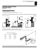
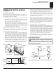
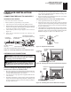
Figure 22 - Vertical Venting Configuration Using One 90° Elbow
(Vertical Round High Wind Termination Shown)
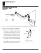
Venting with Two 90° Elbows
Vertical (V
1
) Horizontal (H)
5' min. 6' max.
6' min. 12' max.
7' min. 18' max.
8' min. 20' max.
Note: Vertical (V
1
) + Vertical (V
2
) = 40' max.
Figure 23 - Vertical Venting Configuration Using Two 90° Elbows
(Vertical Round High Wind Termination Shown)
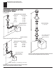
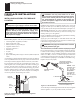
Vertical Venting
V = 40' max.
Figure 24 - Vertical Venting Configuration With No Horizontal
Run (Vertical Round High Wind Termination Shown)
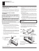
Venting with One 90° Elbow
Vertical (V) Horizontal (H)
5' min. 2' max.
6' min. 4' max.
7' min. 6' max.
8' min. 8' max.
20' max. 8' max.
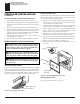
Note: Install restrictor
into inner collar of
fireplace as shown.
45° Elbow
Note: Install restrictor
into inner collar of
fireplace as shown.
45° Elbow
Note: Install restrictor
into inner collar of
fireplace as shown.
45° Elbow