
DIRECT-VENT FIREPLACE OWNER'S OPERATION AND INSTALLATION MANUAL PENINSULA MODELS (V)DVF36 TPNA-A(-HA)/TPNPA-A/TPNEA-A/TPNPEA-A SEE-THRU MODELS (V)DVF36 TSTA-A(-HA)/TSTPA-A/TSTEA-A/TSTPEA-A


www.desatech.com
56131-F22
INSTALLATION
Continued
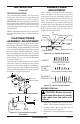
You may test the blower for operation by turning
the control knob clockwise just until it clicks on
which is the full on position. Adjust the fan speed
to the lowest setting (this should be no more than
1/4 of a turn clockwise).
FRONT
O
F
F
P
I
L
O
T
O
N
L
O
H
I
P
I
L
O
T
E A
16AI
7
TPTH TP TH
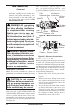
Figure 38 - Installing Remote Receiver
(HRC100)
Gas
Valve
To Thermopoile
Receiver Clip
Terminal
Wires
Plastic Mounting Clips
9-Volt Battery
White
Red
OPTIONAL WIRELESS HAND-HELD
REMOTE CONTROL INSTALLATION
Note: If using an optional wireless hand-held
remote control, the wall switch is no longer
operational.
-
1. Remove lower louver access panel in re-
place (see step 1 of Wall Switch Installation,
page 21).
2. Disconnect wall switch wires from termi-
nals marked TH and TPTH (see Figure 35,
page 21).
3. Slide 9-volt battery into clip on back of remote
receiver and connect battery terminals to bat-
tery. Mount receiver onto bracket with clips
provided (see Figure 38).
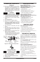
9-Volt Battery
Battery
Housing
Figure 39 - Installing Battery in Hand-
Held Remote Control Unit (HRC100)
Battery
Cover
Terminal
Wires
Remote Control Unit
Sensor
Tag
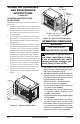
Figure 37 - Connecting Blower
Accessory to Power Supply
For Optional
Fan Kit
From Blower
Assembly
4. Connect white wire to control valve terminal
TH and red wire to TPTH. Move remote select
switch to REMOTE position.
5. Replace louvered access panel by following
reverse steps on page 21.
6. Remove battery cover on back of hand-held
remote (see Figure 39). Remove and discard
sensor tag.
7. Attach terminal wires to 9-volt batter. Place
battery into housing.
8. Replace battery cover onto hand-held remote.
9. Set selector switch on receiver to OFF posi-
tion if you will be away from the unit for an
extended period of time.
1. Remove lower louver access panel in re-
place (see step 1 of Wall Switch Installation,
page 21).
2. If a wall switch was installed, it must be
removed from ignition control circuit for
remote to work properly. Remove wire nuts
from switch connection at ignition control
module. Using wire nut, connect transformer
(blue) wire to remaining wire connected to
control terminal marked P.SW (see Figure
34, page 21).
3. The receiver does not require a battery. To in-
stall, plug extension cord into one of the outlet
receptacles on the outlet box. Plug receiver unit
into extension cord and the ignition module into
receiver unit (see Figure 40, page 23).
4. Replace louvered access panel by following
reverse steps on page 21.
5. Activate handset battery by removing insulat-
ing tab on back (see Figure 41, page 23).