DIRECT-VENT Fireplace OWNER’S OPERATION AND INSTALLATION MANUAL NATURAL GAS “TUDOR” MODELS (V)T32N-A SERIES and CGDV32NR PROPANE/LP GAS “TUDOR” MODELS (V)T32P-A SERIES and CGDV32PR WARNING: If the information in this manual is not followed exactly, a fire or explosion may result causing property damage, personal injury or loss of life. — Do not store or use gasoline or other flammable vapors and liquids in the vicinity of this or any other appliance.
Table of Contents Safety Information................................................ 2 Product Identification............................................ 4 Local Codes......................................................... 4 Product Features.................................................. 4 Pre-Installation Preparation.................................. 5 Location of Termination Cap................................. 7 Venting Installation Instructions............................ 8 Fireplace Installation..
Safety Information Continued Carbon Monoxide Poisoning: Early signs of carbon monoxide poisoning resemble the flu, with headaches, dizziness or nausea. If you have these signs, the fireplace may not be working properly. Get fresh air at once! Have fireplace serviced. Some people are more affected by carbon monoxide than others. These include pregnant women, people with heart or lung disease or anemia, those under the influence of alcohol and those at high altitudes.
SAFETY INFORMATION Continued 9. Do not use this fireplace to cook food or burn paper or other objects. 10. This appliance, when installed, must be electrically grounded in accordance with local codes or, in the absence of local codes, with the National Electrical Code, ANSI/NFPA 70 or the Canadian Electrical Code, CSA C22.1. 11. Do not use fireplace if any part has been under water. Immediately call a qualified service person to arrange for replacement of the unit. 12.
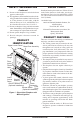
Pre-Installation Preparation Location and space requirements Determine the safest and most efficient location for your DESA direct-vent fireplace. Make sure that rafters and wall studs are not in the way of the venting system. Choose a location where the heat output is not affected by drafts, air conditioning ducts, windows or doors. Figure 2 shows some common locations. Be aware of all restrictions and precautions before deciding the exact location for your fireplace and termination cap.
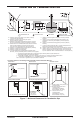
Pre-Installation Preparation Continued 13B5/8" NOTICE: This fireplace is intended for use as supplemental heat. Use this fireplace along with your primary heating system. Do not install this fireplace as your primary heat source. If you have a central heating system, you may run system’s circulating blower while using fireplace. This will help circulate the heat throughout the house. In the event of a power outage, you can use this fireplace as a heat source. 28 / " 97/8" E 323/8" 17" Horiz.
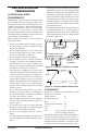
Location of Termination Cap N N D H V L E B C Fixed Closed F B Openable Fixed Closed V Openable V I V G B V B B J X V G G M A V K X V A G GAS METER RESTRICTED AREA V TERMINATION CAP X AIR SUPPLY INLET (TERMINATION PROHIBITED) A = clearance above grade, veranda, porch, deck, or balcony I = clearance to service regulator vent outlet [*72 inches (182.9cm) [*12 inches (30.
Venting Installation Instructions NOTICE: Read these instructions completely before attempting installation. These models are tested and approved for use with DESA (direct-vent) pipe components and terminations. The venting system must terminate on the outside of the structure and can not be attached to a chimney or flue system serving a separate solid fuel or gas burning appliance. A direct-vent appliance must have its own venting system. DO NOT common vent this appliance.
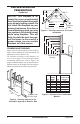
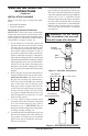
Venting Installation instructions Continued INSTALLATION PLANNING There are two basic types of direct-vent installation: • Horizontal Termination • Vertical Termination Horizontal Termination Installation IMPORTANT: Horizontal square terminations require only inner portion of wall firestop. Horizontal installations using round termination require exterior portion of wall firestop available only in vent kit HTK (see Figure 14, page 11). 1.
Venting Installation instructions Continued 6. Noncombustible Exterior Wall: Position the horizontal vent cap in the center of the 8 1/2" round hole and attach to the exterior wall with four screws (see page 10). Note: The four wood screws provided should be replaced with appropriate fasteners for stucco, brick, concrete or other types of sidings.
Venting Installation instructions Continued Siding Standoff Minimum Pipe Overlap 11/4" Screws GROUND FLOOR INSTALLATION Recommended Applications: • Installation using cabinet surrounds • Through the wall using round or square termination (up to 12") horizontal pipe) • NOT FOR CORNER INSTALLATION Wall Firestop Direct Vent Pipe High Wind Termination Maintain 1" Minimum Air Space Around Outer Pipe When Penetrating a Wall 10 3/4" x 10 3/4" Framed Opening WARNING: Never run vent downward as this may caus
Venting Installation instructions Continued CORNER INSTALLATION Recommended Applications: • Corner ground floor installation • Ground floor installation where pipe vents horizontally through wall (over 12" horizontal pipe) • Basement installation where one foot clearance from ground to termination is possible Not to Exceed 90° Elbow Not to Exceed Square (H) Limits (H) Limits Termination Square As Required 90° Termination for (V), See Elbow Chart for Pipe Section Required Wall Firestop Wall Firestop 45° Elb
Venting Installation instructions Continued HORIZONTAL SYSTEM INSTALLATION USING TWO 90° ELBOWS The following configurations show the minimum vertical rise requirements for a horizontal system using two 90° elbows. Venting with Two 90° Elbows Horizontal (H1) + Vertical (V) Horizontal (H1) Horizontal (H2) 5' min. 2' max. 6' max. 6' min. 4' max. 12' max. 7' min. 6' max. 18' max. 8' min. 8' max. 20' max. 20' max. 8' max. 20' max.
Venting Installation instructions Continued installation for vertical termination Note: Vertical restrictor must be installed in all vertical installations. 1. Determine the route your vertical venting will take. If ceiling joists, roof rafters or other framing will obstruct the venting system, consider an offset (see Figure 19) to avoid cutting load bearing members.
Venting Installation instructions Venting with One 90° Elbow Vertical (V) Horizontal (H) 5' min. 2' max. 6' min. 4' max. 7' min. 6' max. 8' min. 8' max. 20' max. 8' max. 45° Elbow Continued 6. Continue to add pipe sections until the height of the vent cap meets the minimum building code requirements described in Figure 7 on page 8. Note: You must increase vent height for steep roof pitches.
Venting Installation instructions Continued Vertical Venting V = 40' max. Note: Install restrictor into inner collar of fireplace as shown. 45° Elbow Figure 24 - Vertical Venting Configuration With No Horizontal Run (Vertical Round High Wind Termination Shown) High Altitude Installation Your DESA direct-vent fireplace has been tested and approved for elevations from 0-2000 feet (USA) and elevations from 0-4500 feet (Canada).
Venting Installation instructions Continued Number VKR-58 Description Roof Vent Kit, Galvanized (Includes: 45° Elbow, 7"-12" Adjustable Pipe, Flue Restrictor, Vertical High Wind Termination, 2' Pipe, 4' Pipe, Wall Firestop, Storm Collar, Roof Flashing [0/12 - 6/12], 26 Screws) VKC-58 Corner Vent Kit, Galvanized (Includes 45° Elbow, 7"-12" Adjustable Pipe, Wall Firestop, Horizontal Termination, 6" Pipe, 90° Elbow, 18 Screws) HHTK-58 High Wind Round Horizontal Termination Kit (Includes Round Termination, Wa
Fireplace Installation Switch Bracket Continued al ffO kc kc B B al kc W ih et al B 1 01 1/ .V 51 .A .C B al kc hW i et erG ne 18 nO 9. Check to make sure that the power cord is completely clear of the blower wheel and that there are no other foreign objects in blower wheel. Turn blower on and check for operation. Turn blower off by turning knob fully counterclockwise before continuing. 10.
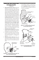
Fireplace Installation Continued 3. Place the blower against the lower rear wall of the firebox outer wrapper with the exhaust port directed upward and the thermodisc positioned up near the fireplace bottom. The thermodisc must be oriented near the fireplace bottom as shown in Figure 29, in order to sense temperature and properly operate. The blower will be held in position against the back wall by the magnets incorporated onto the blower housing (see Figure 29). 4.
Fireplace Installation Continued Installing Gas Piping to Fireplace Location WARNING: A qualified service person must connect fireplace to gas supply. Follow all local codes. CAUTION: For propane/LP units, never connect fireplace directly to the propane/LP supply. This heater requires an external regulator (not supplied). Install the external regulator between the fireplace and propane/LP supply. WARNING: For natural gas, never connect heater to private (non-utility) gas wells.
Fireplace Installation To Gas Supply (Natural) Continued We recommend that you install a sediment trap/drip leg in supply line as shown in Figure 32. Locate sediment trap/drip leg where it is within reach for cleaning. Install in piping system between fuel supply and fireplace. Locate sediment trap/drip leg where trapped matter is not likely to freeze. A sediment trap traps moisture and contaminants. This keeps them from going into fireplace gas controls.
Fireplace Installation Continued Test Pressures Equal To or Less Than 1/2 PSIG (3.5 kPa) 1. Close equipment shutoff valve (see Figure 34). 2. Pressurize supply piping system by either opening propane/LP supply tank valve for propane/LP gas fireplace or opening main gas valve located on or near gas meter for natural gas fireplace or using compressed air. 3. Check all joints from propane/LP supply tank for propane/LP or gas meter for natural gas to equipment shutoff valve (see Figure 35 or Figure 36).
Fireplace Installation Remote Control Unit Battery Cover Continued Installing Optional Wireless hand-held REMOTE CONTROL HRC100 and HRC200 Series NOTICE: Use only alkaline batteries (not included). Installing Remote Receiver 1. Open bottom louver and locate the switch bracket on the left. 2. Unscrew the switch bracket. Lean bracket forward so you are able to access the back of the remote receiver. 3. Locate the battery clip mounted on the back of the receiver.
Fireplace Installation Installing Optional Brick liner Model BL32D Continued Removing Glass Door If replacement of glass is necessary, the entire assembly, glass and frame, must be replaced. If glass is broken, wear gloves and tape the remaining fragments onto the frame. 1. Remove screen assembly by pushing the rod either left or right and then down and forward to remove screen/rod assembly from the firebox. Set assembly aside. 2. Lift up on latches to unlock.
Fireplace Installation 1 Continued 9. Follow instructions below to install logs, lava rock and ember material. 10. Close glass door, lock latches on top and bottom of door and replace screen (see steps 5 and 6 of Removing Glass Door, page 24). 11. Close top and bottom louvers. Figure 45 - Installing Log No. 1 Left Side Brick Panel 2 Figure 44 - Installing Side Brick Panels Installing logs, lava rock and glowing embers Each log is marked with a number.
Fireplace Installation Continued 6. Place log #6 (left log) onto two pins on the left side of back and front log. See Figure 49. 7. Place lava rock along sides and front of firebox bottom in areas that are visible only. It is not necessary to use all of the lava rock provided. 8. Pull ember material apart into pieces no larger than a dime. Place these pieces loosely and sparingly directly onto the exposed section of the front burner and along the space between the burner and grate prongs (see Figure 50).
OPERATIng fireplace TO TURN OFF GAS TO APPLIANCE Continued LIGHTING INSTRUCTIONS 1. STOP! Read the safety information on page 26, column 2. 2. Open lower louver panel. 3. Turn off all electric power to the fireplace. 4. Push in gas control knob slightly and turn clockwise to OFF. 5. Wait five (5) minutes to clear out any gas. Then smell for gas, including near the floor. If you smell gas, STOP! Follow “B” in the safety information on page 26, column 2. If you don't smell gas, go to the next step. 6.
OPERATIng fireplace Continued IMPORTANT: Do not leave the selector switch in the REMOTE or ON position when the pilot is not lit. This will drain the battery.
OPERATIng fireplace Continued Safety Features When away from home for an extended period of time or as a child safety feature to prevent accidental ignition of the fireplace, the receiver ON/OFF/REMOTE switch should be in the OFF position. Auto Shutoff Feature 1. If the average room temperature exceeds 82 degrees Fahrenheit (28 degrees Centigrade), the hand-held remote control will perform a safety override and shut the fireplace off. This feature is not available in the MANU mode. 2.
Inspecting Burners Continued If you pilot assembly does not meet these requirements: • turn fireplace off (see To Turn Off Gas to Appliance, page 28) • see Troubleshooting, page 32 BURNER FLAME PATTERN Burner flames will be steady; not lifting or floating. Flame patterns will be different from unit to unit and will vary depending on installation type and weather conditions. If the vent configuration is installed incorrectly, the flames will lift or "ghost". This can be dangerous.
Cleaning and Maintenance Continued Use only the tempered glass door replacement intended for this fireplace (see Replacement Parts, page 36 for detail on ordering). No substitutions may be made. See Removing/Replacing Glass Door, page 23 for instructions for replacing glass door. WARNING: Do not operate fireplace with the glass door unlatched, removed, cracked or broken. pilot and burners • Remove ember material before cleaning burners and replace when cleaning is complete.
Troubleshooting WARNING: Turn off heater and let cool before servicing. Only a qualified service person should service and repair heater. CAUTION: Never use a wire, needle or similar object to clean pilot. This can damage pilot unit. Note: All troubleshooting items are listed in order of operation. OBSERVED PROBLEM POSSIBLE CAUSE REMEDY When ignitor button is pressed, 1. Ignitor electrode not con- 1. Reconnect ignitor cable there is no spark at pilot nected to ignitor cable 2.
TROUBLESHOOTING Continued OBSERVED PROBLEM POSSIBLE CAUSE Pilot lights but flame goes out when control knob is released 1. Gas control knob not fully 1. Press in gas control knob pressed in fully 2. Gas control knob not pressed 2. After pilot lights, keep gas in long enough control knob pressed in 30 seconds 3. Equipment shutoff valve not 3. Fully open equipment shutoff fully open valve 4. Pilot flame not touching 4.
TROUBLESHOOTING Continued OBSERVED PROBLEM POSSIBLE CAUSE Heater produces a whistling noise when burner is lit 1. Turning gas control knob to 1. Turn gas control knob to LO HI position when burner is position and let warm up for a cold minute 2. Air in gas line 2. Operate burner until air is removed from line. Have gas line checked by local propane/ LP or natural gas company 3. Dirty or partially clogged 3.
TROUBLESHOOTING Continued WARNING: If you smell gas • Shut off gas supply. • Do not try to light any appliance. • Do not touch any electrical switch; do not use any phone in your building. • Immediately call your gas supplier from a neighbor’s phone. Follow the gas supplier’s instructions. • If you cannot reach your gas supplier, call the fire department. OBSERVED PROBLEM POSSIBLE CAUSE REMEDY Fireplace produces unwanted odors 1. Gas leak. See Warning statement above 1.
Replacement Parts Note: Use only original replacement parts. This will protect your warranty coverage for parts replaced under warranty. Parts Under Warranty Contact authorized retailers of this product. If they can not supply original replacement part(s), call DESA’s Technical Service Department at 1-866-672-6040.
Accessories NOTICE: All accessories may not be available for all fireplace models. Purchase these fireplace accessories from your local retailer. If they can not supply these accessories, call DESA’s Sales Department at 1-866-672-6040. for information. You can also write to the address listed on the back page of this manual. Brick Liner (Not Shown) BL32D - Refractory Brick Liner Kit This brick liner adds a touch of style to your directvent fireplace.
Illustrated Parts Breakdown Models (V)T32N-A, (V)T32NB-A, (V)T32NR-A, (V)T32NRB-A, (V)T32P-A, (V)T32PB-A, (V)T32PR-A, (V)T32PRB-A, CGDV32NR and CGDV32PR 22-3 6 22-4 22-5 22-6 22-1 7 22-2 8 4 1 11 14 9 17 21 15 12 13 16 16 2 20 19 18 10 3 5 38 www.desatech.
PARTS LIST This list contains replaceable parts used in your fireplace. When ordering parts, follow the instructions listed under Replacement Parts on page 36 of this manual. PART NUMBER KEY NO.
illustrated parts breakdown Burner assembly Models (V)T32N-A, (V)T32NB-A, (V)T32NR-A, (V)T32NRB-A, (V)T32P-A, (V)T32PB-A, (V)T32PR-A, (V)T32PRB-A, CGDV32NR and CGDV32PR 17 19 16 15 1 2 13 8 3 7 18 9 14 11 6 12 4 5 10 40 www.desatech.
PARTS LIST Burner assembly Models (V)T32N-A, (V)T32NB-A, (V)T32NR-A, (V)T32NRB-A, (V)T32P-A, (V)T32PB-A, (V)T32PR-A, (V)T32PRB-A, CGDV32NR and CGDV32PR This list contains replaceable parts used in your fireplace. When ordering parts, follow the instructions listed under Replacement Parts on page 36 of this manual. KEY NO. 1 2 3 4 5 6 7 8 9 10 11 12 13 14 15 16 17 18 19 PART NO.
NOTES _____________________________________________________ _____________________________________________________ _____________________________________________________ _____________________________________________________ _____________________________________________________ _____________________________________________________ _____________________________________________________ _____________________________________________________ _____________________________________________________ ___________________
NOTES _____________________________________________________ _____________________________________________________ _____________________________________________________ _____________________________________________________ _____________________________________________________ _____________________________________________________ _____________________________________________________ _____________________________________________________ _____________________________________________________ ___________________
Warranty Information KEEP THIS WARRANTY Model Serial No. Date Purchased Always specify model and serial numbers when communicating with the factory. We reserve the right to amend these specifications at any time without notice. The only warranty applicable is our standard written warranty. We make no other warranty, expressed or implied.