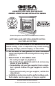
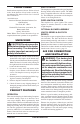
UNVENTED (VENT-FREE) GAS FIREPLACE OWNER’S OPERATION AND INSTALLATION MANUAL Patent Pending Shown with optional cabinet mantel and hearth base accessories. LMFP33NR(A) AND LMFP33PR(A) REMOTE CONTROL GAS FIREPLACE SYSTEMS WARNING: If the information in this manual is not followed exactly, a fire or explosion may result causing property damage, personal injury, or loss of life. — Do not store or use gasoline or other flammable vapors and liquids in the vicinity of this or any other appliance.
WARNING: Improper installation, adjustment, alteration, service, or maintenance can cause injury or property damage. Refer to this manual for correct installation and operational procedures. For assistance or additional information consult a qualified installer, service agency, or the gas supplier. WARNING: This is an unvented gas-fired heater. It uses air (oxygen) from the room in which it is installed. Provisions for adequate combustion and ventilation air must be provided.
SAFETY INFORMATION WARNING: This product contains and/or generates chemicals known to the State of California to cause cancer or birth defects, or other reproductive harm. IMPORTANT: Read this owner’s manual carefully and completely before trying to assemble, operate, or service this heater. Improper use of this heater can cause serious injury or death from burns, fire, explosion, electrical shock, and carbon monoxide poisoning.
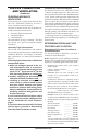
PRODUCT IDENTIFICATION 4-Piece Log Set ON FF T Control Knob O 1. This appliance is only for use with the type of gas indicated on the rating plate. This appliance is not convertible for use with other gases. 2. Do not place propane/LP supply tank(s) inside any structure. Locate propane/LP supply tank(s) outdoors (propane/LP units only). 3.
LOCAL CODES SAFETY DEVICE Install and use fireplace with care. Follow all local codes. In the absence of local codes, use the latest edition of The National Fuel Gas Code ANSI Z223.1/NFPA 54*. *Available from: American National Standards Institute, Inc. 1430 Broadway New York, NY 10018 National Fire Protection Association, Inc. Batterymarch Park Quincy, MA 02269 Note: Where listed vented decorative logs are required, thermostat operation is not permitted.
AIR FOR COMBUSTION AND VENTILATION Continued PROVIDING ADEQUATE VENTILATION The following are excerpts from National Fuel Gas Code, ANSI Z223.1/NFPA 54, Section 5.3, Air for Combustion and Ventilation. All spaces in homes fall into one of the three following ventilation classifications: 1. Unusually Tight Construction 2. Unconfined Space 3. Confined Space The information on pages 5 through 7 will help you classify your space and provide adequate ventilation.
AIR FOR COMBUSTION AND VENTILATION Continued Example: 40,000 Btu/Hr Gas water heater __________ 33,000 Btu/Hr Vent-free fireplace + ________ 73,000 Btu/Hr Total = ________ 4. Compare the maximum Btu/Hr the space can support with the actual amount of Btu/Hr used.
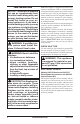
INSTALLATION NOTICE: This heater is intended for use as supplemental heat. Use this heater along with your primary heating system. Do not install this heater as your primary heat source. If you have a central heating system, you may run system’s circulating blower while using heater. This will help circulate the heat throughout the house. In the event of a power outage, you can use this heater as your primary heat source. WARNING: A qualified service person must install fireplace. Follow all local codes.
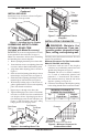
INSTALLATION Continued INSTALLING HOOD Trim Hanging Screws Install hood to top of firebox as shown in Figure 5. Use 3 Phillips screws provided Hanging Notches on Trim Assembled Brass Trim Figure 7 - Attaching Brass Trim to Fireplace Figure 5 - Installing Hood to Firebox ASSEMBLING AND ATTACHING OPTIONAL BRASS TRIM (Included with Mantel Accessory) IMPORTANT: If you are recessing the firebox in a wall, do not attach brass trim at this time. See page 11.
INSTALLATION Continued CONVENTIONAL FIREPLACE INSTALLATION Conventional installation of this fireplace involves installing fireplace along with the corner, face, or cabinet mantel with hearth base accessories against a wall in your home. Follow the instructions below to install the fireplace in this manner. Note: The instructions in this section show installation using the cabinet mantel and hearth base accessories. The hearth base accessory shown is optional for this installation.
INSTALLATION 4. Connect wires from the electrical box to duplex outlet. Match wire colors to those indicated on duplex outlet. Be sure to connect ground wire. 5. Install shield to end of right support bracket and behind the firebox wrapper with 2 screws provided (see Figure 16, page 12). 6. Plug blower cord into duplex outlet. 7. Replace bottom of firebox and reconnect remote receiver module to valve.
INSTALLATION Continued 8. Install gas piping to fireplace location. This installation includes an approved flexible gas line (if allowed by local codes) after the equipment shutoff valve. The flexible gas line must be the last item installed on the gas piping. See Installing Gas Piping to Fireplace Location, page 13. 9. Carefully set fireplace in front of rough opening with back of fireplace inside wall opening. 10. Attach flexible gas line to gas supply. See Connecting Fireplace to Gas Supply, page 15. 11.
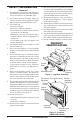
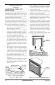
INSTALLATION Continued Wall board or facing material (above firebox) may be of combustible material, including decorative mantel ornaments or other similar projections off of the facing material. Framing Material Mantel Shelf 10" 8" 6" 2 1/2" Firebox Wire-mesh Screen Noncombustible Material May Project Off this Surface above the Firebox 13" 16" 19" 21" Hood Supplied Firebox Hood Must Be Used at All Times Note: All vertical measurements are from top of fireplace hood opening to bottom of mantel shelf.
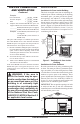
INSTALLATION External Regulator Continued Propane/LP Supply Tank For propane/LP units, the installer must supply an external regulator. The external regulator will reduce incoming gas pressure. You must reduce incoming gas pressure to between 11 and 14 inches of water. If you do not reduce incoming gas pressure, heater regulator damage could occur. Install external regulator with the vent pointing down as shown in Figure 19. Pointing the vent down protects it from freezing rain or sleet.
Screw F CAUTION: Do not pick up log base assembly by burner. This could damage burner. Only handle base by grates. Screw Unplug From Remote Remote Receiver Receiver Module Module Figure 21 - Removing Log Base Assembly From Fireplace To Fireplace Gas Regulator 4. Route gas line (provided by installer) from equipment shutoff valve to fireplace. Route flexible gas supply line through one of the access holes. NOTICE: Most building codes do not permit concealed gas connections.
INSTALLATION Continued CHECKING GAS CONNECTIONS WARNING: Test all gas piping and connections, internal and external tonit, for leaks after installing or servicing. Correct all leaks at once. WARNING: Never use an open flame to check for a leak. Apply a noncorrosive leak detection fluid to all joints. Bubbles forming show a leak. Correct all leaks at once. CAUTION: Make sure external regulator has been installed between propane/LP supply and fireplace.
INSTALLATION Continued Pressure Testing Fireplace Gas Connections 1. Open equipment shutoff valve (see Figure 23, page 16). 2. Open main gas valve located on or near gas meter for natural gas or open propane/LP supply tank valve. 3. Make sure control knob of fireplace is in the OFF position. 4. Check all joints from equipment shutoff valve to gas control valve (see Figures 24 or 25, page 16). Apply noncorrosive leak detection fluid to all joints. Bubbles forming show a leak. 5. Correct all leaks at once. 6.
INSTALLATION WARNING: You must operate this fireplace with the fireplace screen in place. Make sure fireplace screen is in place before running fireplace. Continued Left Top Log (#4) P ILOT Figure 28 - Installing Top Logs Models LMFP33PRA and LMFP33NRA 1. Place the base of the middle log (#1) in the U-shaped slots of the grate base. The cutout on the right of the middle log should fit over the burner (see Figure 29).
INSTALLATION OPERATING HEATER Continued INSTALLING BATTERIES FOR REMOTE RECEIVER AND HAND HELD REMOTE CONTROL Four AA batteries and three AAA batteries are required to operate this heater with the wireless hand-held remote control set. Four AA batteries must be installed in the receiver and three AAA batteries in the hand-held remote control unit. Note: Only use alkaline batteries. Installing Batteries in Receiver 1. Locate slot on battery cover of receiver (see Figure 33).
OPERATING HEATER Continued LIGHTING INSTRUCTIONS WARNING • If fireplace has glass doors, never operate this heater with glass doors closed. If you operate heater with doors closed, heat buildup inside fireplace will cause glass to burst. Make sure there are no obstructions across opening of fireplace. • You must operate this heater with a fireplace screen in place. Make sure fireplace screen is closed before running heater.
OPERATING HEATER Continued 9. Slightly push in and turn control knob counterclockwise to the ON position. 10. Press the on/off key on the remote control to turn on appliance main burner. Wait at least 5 seconds before setting desired flame height. 11. Press the up or down key until the small triangle is to the left of large flame icon at the top of LCD display (see Figure 38). Press the left or right key to set the desired flame height.
OPERATING HEATER INSPECTING BURNERS Continued Check pilot flame pattern and burner flame patterns often. Setting Room Temperature Press the up or down key until the small triangle is to the left of the thermometer icon (see Figure 38, page 21). Press the left or right key to set the desired room temperature. Setting Timer (Sleep Function) Press the up or down key until the small triangle is to the left of the clock icon (see Figure 38, page 21). Press the left or right key to set the desired sleep time.
INSPECTING BURNERS Continued BURNER PRIMARY AIR HOLES Air is drawn into the burner through the holes in the fitting at the burner entrance. These holes may become blocked with dust or lint. Periodically inspect these holes for any blockage and clean if needed. Blocked air holes will create soot. MAIN BURNER Periodically inspect all burner flame holes with the fireplace running. All slotted burner flame holes should be open with yellow flame present.
CLEANING AND MAINTENANCE Continued 1. Shut off the unit, including the pilot. Allow the unit to cool for at least thirty minutes. 2. Inspect burner, pilot, and primary air inlet holes on injector holder for dust and dirt (see Figures 43 and 44). 3. Blow air through the ports/slots and holes in the burner. 4. Check the injector holder located at the end of the burner tube again. Remove any large particles of dust, dirt, lint, or pet hair with a soft cloth or vacuum cleaner nozzle. 5.
TROUBLESHOOTING WARNING: Turn off heater and let cool before servicing. Only a qualified service person should service and repair heater. CAUTION: Never use a wire, needle, or similar object to clean ODS/pilot. This can damage ODS/pilot unit. Note: All troubleshooting items are listed in order of operation. OBSERVED PROBLEM POSSIBLE CAUSE When ignitor button is pressed, there is no spark at ODS/pilot 1. Ignitor electrode not con- 1. Reconnect ignitor cable nected to ignitor cable 2.
TROUBLESHOOTING Continued OBSERVED PROBLEM POSSIBLE CAUSE REMEDY ODS/pilot lights but flame goes out when control knob is released 1. Control knob not fully pressed in 2. Control knob not pressed in long enough 3. Equipment shutoff valve not fully open 4. Pilot flame not touching thermocouple, which allows thermocouple to cool, causing pilot flame to go out. This problem could be caused by one or both of the following: A) Low gas pressure B) Dirty or partially clogged ODS/pilot 5.
TROUBLESHOOTING Continued OBSERVED PROBLEM POSSIBLE CAUSE Moisture/condensation noticed on windows 1. Not enough combustion/ven- 1. Refer to Air for Combustion tilation air and Ventilation requirements (page 5) Heater produces a whistling noise when burners are lit 1. Turning control knob to HI po- 1. Turn control knob to LO position when burners are cold sition and let warm up for a minute 2. Air in gas line 2. Operate burners until air is removed from line.
TROUBLESHOOTING Continued WARNING: If you smell gas • Shut off gas supply. • Do not try to light any appliance. • Do not touch any electrical switch; do not use any phone in your building. • Immediately call your gas supplier from a neighbor’s phone. Follow the gas supplier’s instructions. • If you cannot reach your gas supplier, call the fire department. IMPORTANT: Operating fireplace where impurities in air exist may create odors.
SPECIFICATIONS LMFP33NR/A 23,000/33,000 Natural Gas Piezo 3.5" W.C. Btu (Variable) Type Gas Ignition Pressure Manifold Inlet Gas Pressure (in. of water) Maximum 10.5" Minimum* 5.5" Shipping Weight 122 lbs. * For input adjustment WIRING DIAGRAM 14" 11" 122 lbs.
ILLUSTRATED PARTS BREAKDOWN MODELS LMFP33PR, LMFP33PRA, LMFP33NR AND LMFP33NRA (SHOWN) “A Models” 1b 1d 1b 1a 1a 1c 1c 2 1d 4 6 3 1e 7 5 8 9 14 4 27 15 10 28 16 22 11 19 13 12 18 17 23 24 26 20 21 25 30 www.desatech.
PARTS LIST This list contains replaceable parts used in your fireplace. When ordering parts, follow the instructions listed under Replacement Parts on page 29 of this manual. KEY PART NUMBER NO.
ILLUSTRATED PARTS BREAKDOWN FIREBOX LMFP33PR, LMFP33PRA, LMFP33NR AND LMFP33NRA 6 1 7 2 4 10 3 9 9 12 14 14 14 9 13 5 14 15 8 16 14 11 32 www.desatech.
PARTS LIST FIREBOX LMFP33PR, LMFP33PRA, LMFP33NR AND LMFP33NRA This list contains replaceable parts used in your fireplace. When ordering parts, follow the instructions listed under Replacement Parts on page 29 of this manual. KEY NO.
ACCESSORIES NOTICE: All accessories may not be available for all fireplace models. Purchase these fireplace accessories from your local dealer. If they can not supply these accessories, call DESA Heating Productsʼ Sales Department at 1-866-672-6040 for information. You can also write to the address listed on the back page of this manual.
NOTES ______________________________________________________ ______________________________________________________ ______________________________________________________ ______________________________________________________ ______________________________________________________ ______________________________________________________ ______________________________________________________ ______________________________________________________ ______________________________________________________ __________
WARRANTY INFORMATION KEEP THIS WARRANTY Model ______________________________ Serial No. ___________________________ Date Purchased ______________________ Always specify model and serial numbers when communicating with the factory. We reserve the right to amend these specifications at any time without notice. The only warranty applicable is our standard written warranty. We make no other warranty, expressed or implied.