
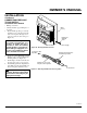
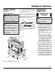
OWNER'S OPERATION AND INSTALLATION MANUAL VENT-FREE PROPANE/LP GAS BAY FRONT FIREPLACE CF26PT


11
107187
OWNER’S MANUAL
For more information, visit www.desatech.com
INSTALLATION
Continued
WARNING: A licensed electri-
cian must connect the wiring har-
ness to electrical supply follow-
ing all local codes. Electrician
must provide a clamp on the box
cover to secure the wiring. Wir-
ing should be routed through the
bushing in the hole on the outer
casing of heater.
1. Install a snap bushing found in hard-
ware kit into one of the holes found on
rear of blower control shield. The other
hole is for a strain relief clamp (not sup-
plied) to secure incoming electrical
supply.
2. Follow steps 2 through 6 in Installing
Blower Assembly, page 10. Also re-
move black wire from middle/OFF
switch terminal.
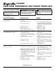
3. Remove black plastic strain relief and
power cord from switch plate (see Fig-
ure 18). The power cord supplied will
not be used in built-in installations. Pop
in the plastic snap bushing found in hard-
ware kit into the hole left by supply cord/
strain relief.
4. A licensed electrician must follow the
wiring diagram in Figure 19 to connect
incoming electrical supply to fan kit
wiring harness.
5. Test to make sure the blower is work-
ing properly.
6. Reinstall hood assembly (see page 9)
and close lower louver door.
7. Place log set back on the unit.
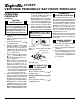
For Built-In Installation
Figure 18 - Installing Blower Bracket Assembly
Figure 19 - Wiring Diagram For Fan Accessory
Built-In Installation
A
U
T
O
O
F
F
O
N
Blower Bracket
Assembly
Screw
Wire
Harness
Power
Cord
Blower
Control
Shield
Shield
Cover
Wire
Harness
Switch
Plate
Switch
Clamp Connector
(not included)
Outlet
Receptacle
Blue
Red
Continued
Blower
Control
Shield
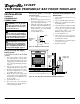
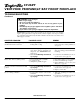
Figure 17 - Installing Switch Plate to
Blower Control Shield
Switch
Plate
Screw
Strain
Relief
Red
Red
Fan Switch
(Auto/Off/On)
Blue
Blue
Thermostat
Switch
(N.O.)
Green
White
Green
White
On
110/115
V.A.C.
Blower
Motor
Black
Off
1
2
3
Auto