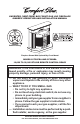
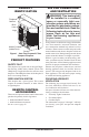
UNVENTED (VENT-FREE) BAY FRONT GAS LOG FIREPLACE OWNER’S OPERATION AND INSTALLATION MANUAL Patent Pending A OTU FF O NO Fireplace Shown With Optional Bay Front Mantel MODELS CF26PRA AND CF26NRA 19,000 TO 26,000 BTU/HR REMOTE CONTROL READY WARNING: If the information in this manual is not followed exactly, a fire or explosion may result causing property damage, personal injury, or loss of life.
WARNING: Improper installation, adjustment, alteration, service, or maintenance can cause injury or property damage. Refer to this manual for correct installation and operational procedures. For assistance or additional information consult a qualified installer, service agency, or the gas supplier. WARNING: This is an unvented gas-fired heater. It uses air (oxygen) from the room in which it is installed. Provisions for adequate combustion and ventilation air must be provided.
SAFETY INFORMATION WARNING: This product contains and/or generates chemicals known to the state of California to cause cancer or birth defects, or other reproductive harm. IMPORTANT: Read this owner’s manual carefully and completely before trying to assemble, operate, or service this fireplace. Improper use of this fireplace can cause serious injury or death from burns, fire, explosion, electrical shock, and carbon monoxide poisoning.
SAFETY INFORMATION Continued 1. This appliance is only for use with the type of gas indicated on the rating plate. This appliance is not convertible for use with other gases. 2. Do not place propane/LP supply tank(s) inside any structure. Locate propane/LP supply tank(s) outdoors (propane/LP units only). 3.
PRODUCT IDENTIFICATION WARNING: This heater shall not be installed in a confined space or unusually tight construction unless provisions are provided for adequate combustion and ventilation air. Read the following instructions to insure proper fresh air for this and other fuel-burning appliances in your home.
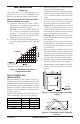
AIR FOR COMBUSTION AND VENTILATION Continued Unusually Tight Construction The air that leaks around doors and windows may provide enough fresh air for combustion and ventilation. However, in buildings of unusually tight construction, you must provide additional fresh air. Unusually tight construction is defined as construction where: a.
AIR FOR COMBUSTION AND VENTILATION 12" Continued The space in the above example is a confined space because the actual Btu/Hr used is more than the maximum Btu/Hr the space can support. You must provide additional fresh air. Your options are as follows: A. Rework worksheet, adding the space of an adjoining room. If the extra space provides an unconfined space, remove door to adjoining room or add ventilation grills between rooms. See Ventilation Air From Inside Building. B.
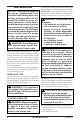
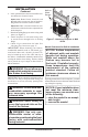
INSTALLATION NOTICE: This heater is intended for use as supplemental heat. Use this heater along with your primary heating system. Do not install this heater as your primary heat source. If you have a central heating system, you may run system’s circulating blower while using heater. This will help circulate the heat throughout the house. In the event of a power outage, you can use this heater as your primary heat source. WARNING: A qualified service person must install fireplace. Follow all local codes.
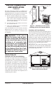
INSTALLATION Continued An optional blower kit is available from your dealer. See Accessories, page 35. If planning to use blower, locate fireplace near an electrical outlet. Minimum Clearances For Side Combustible Material, Side Wall, and Ceiling A. Clearances from the side of the fireplace cabinet to any combustible material and wall should follow diagram in Figure 4. Example: The face of a mantel, bookshelf, etc. is made of combustible material and protrudes 3 1/2" from the wall.
INSTALLATION Continued 6. If the optional blower has been installed connect blower to electrical source. Option one: Route blower electrical cord through side or rear access door of fireplace. Plug electrical cord into electrical outlet. Option two: Have a licensed electrician connect blower to electrical source at junction box inside fireplace. 7. Bend four nailing flanges on outer casing with pliers (see Figure 7). 8. Attach fireplace to wall studs using nails or wood screws through holes in nailing flange.
INSTALLATION Set Screws Continued Note: All vertical measurements are from top of fireplace opening to bottom of mantel shelf. Slot Top Trim Mantel Shelf Shim 10" 8" Adjusting Plate 6" 2 1/2" Mitered Edge Side Trim Slot Figure 9 - Assembling Trim Minimum NonCombustible Material 21" 19" 16" 13" OPTIONAL MANTEL INSTALLATION Figure 8 - Minimum Mantel Clearances for Built-In Installation Note: Refer to instructions provided with the mantel for assembly instructions.
INSTALLATION INSTALLING BLOWER ASSEMBLY GA3450T Continued 3. Assemble trim kit. See Assembling Trim, page 11. 4. Place trim on the shoulder screws located on the side and top of the fireplace. Firmly snap the trim over the shoulder screws on fireplace (see Figure 13). 5. Place mantel base close to wall in desired fireplace location. 6. Install gas line. See Connecting To Gas Supply, page 15 7. Carefully place fireplace on mantel base and center left to right. Check for gas leaks.
INSTALLATION Continued 8. Insert the 4 wire harness into one of the round holes in the rear of the blower control shield and through the rectangular hole in the front of shield (see Figure 15). 9. Reconnect red wire to the AUTO switch position. Reconnect blue wire to the ON switch position. Reconnect green and white wires to the power cord. 10. Install the switch plate on the blower control shield with 2 - #10 screws provided (see Fig- ure 16).
INSTALLATION Continued For Built-In Installation WARNING: A licensed electrician must connect the wiring harness to electrical supply following all local codes. Electrician must provide a clamp on the box cover to secure the wiring. Wiring should be routed through the bushing in the hole on the outer casing of heater.
INSTALLATION Continued WARNING: Never attempt to service heater while it is plugged in, operating, or hot. Burns and electrical shock could result. Only a qualified service person should service or repair heater. If any of the original wire as supplied with the appliance must be replaced, original replacements must be used. DESA part no. 104015-01 (105°C) for power cord, and DESA part no. 103968-01 (200°C) for wire harness. WARNING: Label all wires prior to disconnection when servicing controls.
CONNECTING FIREPLACE TO GAS SUPPLY INSTALLATION Continued Installation must include an equipment shutoff valve, union, and plugged 1/8" NPT tap. Locate NPT tap within reach for test gauge hook up. NPT tap must be upstream from heater (see Figure 20). IMPORTANT: Install equipment shutoff valve in an accessible location. The equipment shutoff valve is for turning on or shutting off the gas to the appliance.
INSTALLATION Continued 3. Check all gas connections for leaks. See Checking Gas Connections. 4. Feed flexible gas line into fireplace base area. Make sure the entire flexible gas line is in fireplace mantel base area. CAUTION: Avoid damage to regulator. Hold gas regulator with wrench when connecting it to gas piping and/or fittings. CHECKING GAS CONNECTIONS WARNING: Test all gas piping and connections, internal and external to unit, for leaks after installing or servicing. Correct all leaks at once.
INSTALLATION Continued PRESSURE TESTING HEATER GAS CONNECTIONS 1. Open equipment shutoff valve (see Figure 23, page 17). 2. Open main gas valve located on or near gas meter for natural gas or open propane/LP supply tank valve. 3. Make sure control knob of heater is in the OFF position. 4. Check all joints from equipment shutoff valve to thermostat gas valve (see Figures 24 and 25, page 17). Apply noncorrosive leak detection fluid to all joints. Bubbles forming show a leak. 5. Correct all leaks at once. 6.
INSTALLATION Receiver Continued 4. Install remote receiver unit onto gas log heater base using clips (2) and insulating washers provided. 5. Push clips firmly into place (see Figure 29). 6. Connect wires as shown in Figure 30.
WARNING: If you do not follow these instructions exactly, a fire or explosion may result causing property damage, personal injury or loss of life. A. This appliance has a pilot which must be lighted by hand. When lighting the pilot, follow these instructions exactly. B. BEFORE LIGHTING smell all around the appliance area for gas. Be sure to smell next to the floor because some gas is heavier than air and will settle on the floor. WHAT TO DO IF YOU SMELL GAS • Do not try to light any appliance.
OPERATING FIREPLACE MANUAL LIGHTING PROCEDURE Continued CAUTION: Do not try to adjust heating levels by using the equipment shutoff valve. WARNING: Make sure the selector switch is in the OFF position when you are away from home for long periods of time. Heater will come on automatically with selector switch in the ON position.
OPERATING FIREPLACE Continued ON/OFF SERIES (MODEL CGHRCB) Hold the control button on the hand-held remote until burner turns on. Hold the control button again until burner turns off (see Figure 37). TO LOCK press both buttons on hand-held remote control until light stops flashing. Handheld remote control is now locked. If the fire is on it will be turned off automatically. In the locked state, the light will not light up when any button is pressed.
INSPECTING BURNERS Check pilot flame pattern and burner flame patterns often. Approx. 3-6" Above Top of Logs PILOT FLAME PATTERN Figure 39 shows a correct pilot flame pattern. Figure 40 shows an incorrect pilot flame pattern. The incorrect pilot flame is not properly heating the thermocouple. When the thermocouple cools, the heater will shut down.
CLEANING AND MAINTENANCE Continued WARNING: Failure to keep the primary air opening(s) of the burner(s) clean may result in sooting and property damage. CABINET Air Passageways Use a vacuum cleaner or pressurized air to clean. Exterior Use a soft cloth dampened with a mild soap and water mixture. Wipe the cabinet to remove dust.
TROUBLESHOOTING WARNING: Turn off heater and let cool before servicing. Only a qualified service person should service and repair heater. CAUTION: Never use a wire, needle, or similar object to clean ODS/pilot. This can damage ODS/pilot unit. Note: All troubleshooting items are listed in order of operation. OBSERVED PROBLEM POSSIBLE CAUSE REMEDY When ignitor button is pressed, there is no spark at ODS/pilot 1. Ignitor electrode not connected to ignitor cable 2. Ignitor cable pinched or wet 1.
TROUBLESHOOTING OBSERVED PROBLEM ODS/pilot lights but flame goes out when control knob is released Burner does not light after ODS/pilot is lit Continued POSSIBLE CAUSE 1. Control knob not fully pressed in 2. Control knob not pressed in long enough 3. Equipment shutoff valve not fully open 4. Pilot flame not touching thermocouple, which allows thermocouple to cool, causing pilot flame to go out.
TROUBLESHOOTING OBSERVED PROBLEM Continued POSSIBLE CAUSE Moisture/condensation noticed on windows 1. Not enough combustion/ventilation air 1. Refer to Air for Combustion and Ventilation requirements (page 5) Heater produces a whistling noise when burners are lit 1. Turning control knob to HI position when burners are cold 2. Air in gas line 1. Turn control knob to LO position and let warm up for a minute 2. Operate burners until air is removed from line.
TROUBLESHOOTING Continued WARNING: If you smell gas • Shut off gas supply. • Do not try to light any appliance. • Do not touch any electrical switch; do not use any phone in your building. • Immediately call your gas supplier from a neighbor’s phone. Follow the gas supplier’s instructions. • If you cannot reach your gas supplier, call the fire department. IMPORTANT: Operating heater where impurities in air exist may create odors.
SPECIFICATIONS CF26PRA CF26NRA Btu (Variable) 19,000/26,000 Type Gas Propane/LP Ignition Piezo Manifold Pressure 8" W.C. Inlet Gas Pressure (in. of water) * Maximum 14" Minimum 11" Dimensions (H x W x D) Fireplace 25 7/8" x 27" x 13 3/4" Carton 28" x 26 13/16" x 16 1/2" Weight, pounds Fireplace 44.5 lbs. Shipping 55 lbs. 19,000/26,000 Natural Piezo 3.5" W.C. 10.5" 5" 25 7/8" x 27" x 13 3/4" 28" x 26 13/16" x 16 1/2" * For purposes of input adjustment 44.5 lbs. 55 lbs.
ILLUSTRATED PARTS BREAKDOWN MODELS CF26PRA AND CF26NRA 1 3 2 10 6 7 9 4 25 5 10 24 12 11 13 18 H I 14 23 L O P N O ILOT 19 H I 19 O O F O F N L P ILOT 20 30 F 15 8 F 16 O 17 13 22 21 www.desatech.
PARTS LIST This list contains replaceable parts used in your heater. When ordering parts, follow the instructions listed under Replacement Parts on page 34 of this manual. KEY NO.
ILLUSTRATED PARTS BREAKDOWN MODELS CF26PRA AND CF26NRA 1 3 5 4 9 16 16 18 21 6 7 3 15 2 5 18 18 21 19 13 18 17 14 20-1 12 16 11-1 20-2 10 20-3 8 11-2 32 www.desatech.
PARTS LIST MODELS CF26PRA AND CF26NRA This list contains replaceable parts used in your fireplace. When ordering parts, follow the instructions listed under Replacement Parts on page 34 of this manual. KEY NO.
REPLACEMENT PARTS PARTS CENTRAL Note: Use only original replacement parts. This will protect your warranty coverage for parts replaced under warranty. These Parts Centrals are privately owned businesses. They have agreed to support our customerʼs needs by providing original replacement parts and accessories. PARTS UNDER WARRANTY Tool and Equipment, Co. 1348 Dixwell Avenue Hamden, CT 06514-0322 1-800-397-7553 203-248-7553 Parts Department Portable Heater Parts 342 N. County Rd.
ACCESSORIES Purchase these heater accessories from your local dealer or Parts Central (see page 34). If they can not supply these accessories, call DESA Heating Products at 1-866-672-6040 for referral information. You can also write to the address listed on the back page of this manual. EQUIPMENT SHUTOFF VALVE GA5010 For all models. Equipment shutoff valve with 1/8" NPT tap. Fits 1/2" NPT pipe. BRASS ACCENT TRIM - GA7092 (Not Shown) Optional two piece trim kit for the Bayfront Fireplace.
WARRANTY INFORMATION KEEP THIS WARRANTY Model Serial No. Date Purchased Always specify model and serial numbers when communicating with the factory. We reserve the right to amend these specifications at any time without notice. The only warranty applicable is our standard written warranty. We make no other warranty, expressed or implied.