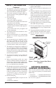
UNVENTED (VENT-FREE) GAS COMPACT CLASSIC HEARTH® DUAL BURNER FIREPLACE OWNER’S OPERATION AND INSTALLATION MANUAL Shown with Optional Cabinet Mantel/Hearth Base Accessory REMOTE-READY MODELS CDCFNRA AND CDCFPRA WARNING: If the information in this manual is not followed exactly, a fire or explosion may result causing property damage, personal injury, or loss of life. — Do not store or use gasoline or other flammable vapors and liquids in the vicinity of this or any other appliance.
WARNING: Improper installation, adjustment, alteration, service, or maintenance can cause injury or property damage. Refer to this manual for correct installation and operational procedures. For assistance or additional information consult a qualified installer, service agency, or the gas supplier. WARNING: This is an unvented gas-fired heater. It uses air (oxygen) from the room in which it is installed. Provisions for adequate combustion and ventilation air must be provided.
SAFETY INFORMATION WARNING: This product contains and/or generates chemicals known to the State of California to cause cancer or birth defects, or other reproductive harm. IMPORTANT: Read this owner’s manual carefully and completely before trying to assemble, operate, or service this fireplace. Improper use of this fireplace can cause serious injury or death from burns, fire, explosion, electrical shock, and carbon monoxide poisoning.
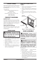
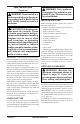
Fireplace Cabinet Hood Logs H L N O F P Remote Control (Optional) I Ignitor Button F 4 PRODUCT IDENTIFICATION O 1. This appliance is only for use with the type of gas indicated on the rating plate. This appliance is not convertible for use with other gases. 2. Do not place propane/LP supply tank(s) inside any structure. Locate propane/LP supply tank(s) outdoors. 3.
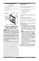
LOCAL CODES Install and use fireplace with care. Follow all local codes. In the absence of local codes, use the latest edition of The National Fuel Gas Code ANSI Z223.1/NFPA 54*. *Available from: American National Standards Institute, Inc. 1430 Broadway New York, NY 10018 National Fire Protection Association, Inc. Batterymarch Park Quincy, MA 02269 PRODUCT FEATURES REMOVING CERAMIC BRICK LINERS 1. Remove screws from top louver and carefully remove louver (see Figure 2). 2.
HOOD ASSEMBLY Continued 3. Locate four black phillips sheet metal screws in hardware packet. 4. Slide hood between louver and firebox top and align screw holes. 5. Insert screws as shown in Figure 3. Tighten screws firmly. Louver Sheet Metal Firebox Screws Top Hood Figure 3 - Assembling Hood AIR FOR COMBUSTION AND VENTILATION WARNING: This fireplace shall not be installed in a confined space or unusually tight construction unless provisions are provided for adequate combustion and ventilation air.
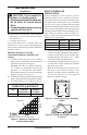
AIR FOR COMBUSTION AND VENTILATION Continued Confined and Unconfined Space The National Fuel Gas Code, ANSI Z223.1/NFPA 54 defines a confined space as a space whose volume is less than 50 cubic feet per 1,000 Btu per hour (4.8 m3 per kw) of the aggregate input rating of all appliances installed in that space and an unconfined space as a space whose volume is not less than 50 cubic feet per 1,000 Btu per hour (4.8 m3 per kw) of the aggregate input rating of all appliances installed in that space.
AIR FOR COMBUSTION AND VENTILATION Continued Ventilation Air From Inside Building This fresh air would come from an adjoining unconfined space. When ventilating to an adjoining unconfined space, you must provide two permanent openings: one within 12" of the ceiling and one within 12" of the floor on the wall connecting the two spaces (see options 1 and 2, Figure 4). You can also remove door into adjoining room (see option 3, Figure 5). Follow the National Fuel Gas Code, ANSI Z223.1/NFPA 54, Section 5.
INSTALLATION Continued WARNING: Never install in a bedroom or bathroom. Any heating product with a Btu/Hr rating over 10,000 cannot be used in a bedroom. CAUTION: This fireplace creates warm air currents. These currents move heat to wall surfaces next to fireplace. Installing fireplace next to vinyl or cloth wall coverings or operating fireplace where impurities (such as, but not limited to, tobacco smoke, aromatic candles, cleaning fluids, oil or kerosene lamps, etc.
INSTALLATION Continued CAUTION: If you install the fireplace in a home garage • fireplace pilot and burner must be at least 18 inches above floor. • locate fireplace where moving vehicle will not hit it. For convenience and efficiency, install fireplace • where there is easy access for operation, inspection, and service • in coldest part of room An optional blower kit is available from your dealer. See Accessories, page 38. If planning to use blower, follow instructions provided with blower for power source.
INSTALLATION Continued WARNING: If pre-wiring, do not connect wiring to any electrical source at this time. Install fireplace electrical outlet and connect wiring to outlet before connecting to electrical source. The fireplace electrical outlet is included with the GA3450TA blower accessory. Only use the fireplace electrical outlet supplied with the GA3450TA blower accessory. Note: A qualified installer should make all electrical connections. 3. Install gas piping to fireplace location.
INSTALLATION OPTIONAL MANTEL INSTALLATION Continued Mantel Clearances for Built-In Installation If placing mantel above built-in fireplace, you must meet minimum clearance between mantel shelf and top of fireplace opening (see Figure 10). NOTICE: Surface temperatures of adjacent walls and mantels become hot during operation. Walls and mantels above the firebox may become hot to the touch. If installed properly, these temperatures meet the requirement of the national product standard.
INSTALLATION Continued 12. Install gas line. See Connecting To Gas Supply, page 16. 13. Check for leaks. See Checking Gas Connections, page 17. 14. Place mantel around fireplace. Be careful not to damage wall or mantel. 15. Place perimeter trim kit on the shoulder screws located on the side and top of the fireplace. Firmly snap trim over shoulder screws on fireplace (see Figure 12). 16. Adjust assembly to remove any gaps.
INSTALLATION Continued Installing Blower Accessory CAUTION: Label all wires prior to disconnection when servicing controls. Wiring errors can cause improper and dangerous operation. CAUTION: Verify proper operation after servicing. Note: If you are using a mantel with your fireplace, use the following instructions. If your fireplace is built-in, see For Built-In Installation, page 15. 1.
INSTALLATION Continued For Built-In Installation WARNING: A licensed electrician must connect the wiring harness to electrical supply following all local codes. Electrician must provide a clamp on the box cover to secure the wiring. Wiring should be routed through the bushing in the hole on the outer casing of fireplace. 1. Install snap bushing from blower kit into one hole on rear of remote/blower bracket (see Figure 17).
INSTALLATION Continued CONNECTING TO GAS SUPPLY WARNING: This appliance requires a 45° male flare fitting 5/8"-18 UNF (Unified National Fine Thread) inlet connection and the flexible gas line provided. WARNING: A qualified service person must connect fireplace to gas supply. Follow all local codes. WARNING: Never connect natural gas fireplace to private (non-utility) gas wells. This gas is commonly known as wellhead gas. IMPORTANT: For natural gas, check gas line pressure before connecting fireplace to gas line.
INSTALLATION Continued CAUTION: Avoid damage to gas control. Hold gas control with wrench when connecting it to gas piping and/or fittings. 4. Check all gas connections for leaks (see Checking Gas Connections). Feed lexible gas line into fireplace. Make sure the entire flexible gas line is in fireplace. 116658-01A H N O ILOT 2. Route flexible gas line, included, from fireplace control to equipment shutoff valve through side access holes in outer casing. 3.
INSTALLATION Gas Control Valve Continued CAUTION: Make sure external regulator has been installed between propane/LP supply and fireplace. See guidelines under Connecting to Gas Supply, page 16. PRESSURE TESTING GAS SUPPLY PIPING SYSTEM Test Pressures In Excess Of 1/2 PSIG (3.5 kPa) 1. Disconnect appliance with its appliance main gas valve (control valve) and equipment shutoff valve from gas supply piping system. Pressures in excess of 1/2 psig will damage heater regulator. 2.
INSTALLATION Continued OPTIONAL WIRELESS HAND-HELD REMOTE CONTROL ACCESSORIES Installing Receiver 1. Disconnect wires from the control valve (see Figure 26). 2. Locate the battery clip mounted on the back of the receiver (see Figure 27). 3. Slide 9-volt battery (not included) through the clip. 4. Attach the terminal wires to the battery (see Figure 27). 5. Connect wires from remote receiver to control valve as shown in Figure 28. 6.
INSTALLATION Terminal “W” Continued W 4. Gently remove the cover of the thermostat from the base. Grasp the sides of the cover firmly and pull to separate from the base. 5. Feed the electrical wires through the rectangular slots on each side of the base (see Figure 31). WARNING: Do not connect the thermostat to a power source. Electrical shock and/or a fire hazard will occur. 6. Connect one bare wire end to each terminal (“W” and “R”) of the thermostat base (see Figure 32). 7.
INSTALLATION Log Set Continued 3. Install left and right brick liners using brackets and screws from hardware kit as shown in Figure 34. Screw the bracket into top of firebox and against brick liners. Adjust bracket before tightening screw. 4. Remove log packaging material and discard. Gently place log over burner (see Figure 35). (Do not allow log to contact flame as this will create sooting.) 5. Insert each rod through ten rings located at top of screen (see Figure 36). 6.
OPERATING FIREPLACE FOR YOUR SAFETY READ BEFORE LIGHTING WARNING: If you do not follow these instructions exactly, a fire or explosion may result causing property damage, personal injury or loss of life. A. This appliance has a pilot which must be lighted by hand. When lighting the pilot, follow these instructions exactly. B. BEFORE LIGHTING smell all around the appliance area for gas. Be sure to smell next to the floor because some gas is heavier than air and will settle on the floor.
OPERATING FIREPLACE TO TURN OFF GAS TO APPLIANCE Continued 6. With control knob pressed in, press and release ignitor button. This will light pilot. The pilot is attached to the front burner. If needed, keep pressing ignitor button until pilot lights. Note: If pilot does not stay lit, contact a qualified service person or gas supplier for repairs. Until repairs are made, light pilot with match. To light pilot with match, see Manual Lighting Procedure. 7.
OPERATING FIREPLACE Continued Note: The burner may light if hand-held remote was on when selector switch was last turned off. You can now turn the burner on and off with the hand-held remote control unit. IMPORTANT: Do not leave the selector switch in the REMOTE or ON position when the pilot is not lit. This will drain the battery.
OPERATING FIREPLACE Continued Note: Do not hold the hand-held remote for a long time. Body temperature will affect its operation in the AUTO mode. Safety Features When away from home for an extended period of time or as a child safety feature to prevent accidental ignition of the fireplace, the receiver ON/OFF/REMOTE switch should be in the OFF position. Auto Shutoff Feature 1.
INSPECTING BURNERS CONTINUED BURNER FLAME PATTERN Figure 45 shows a correct burner flame pattern. Figure 46 shows an incorrect burner flame pattern. The incorrect burner flame pattern shows sporadic, irregular flame tipping. The flame should not be dark or have an orange/reddish tinge. Note: When using the fireplace the first time, the flame will be orange for approximately one hour until the log cures.
CLEANING AND MAINTENANCE WIRING DIAGRAM Continued TPTH TH Gas Control TPTH TP Clean the pilot assembly also. A yellow tip on the pilot flame indicates dust and dirt in the pilot assembly. There is a small pilot air inlet hole about two inches from where the pilot flame comes out of the pilot assembly (see Figures 48 or 49 depending on model). With the unit off, lightly blow air through the air inlet hole. You may blow through a drinking straw if compressed air is not available.
TROUBLESHOOTING WARNING: Turn off and unplug fireplace and let cool before servicing. Only a qualified service person should service and repair fireplace. CAUTION: Never use a wire, needle, or similar object to clean ODS/ pilot. This can damage ODS/pilot unit. Note: All troubleshooting items are listed in order of operation. OBSERVED PROBLEM POSSIBLE CAUSE REMEDY When ignitor button is pressed, there is no spark at ODS/pilot 1. Ignitor electrode not connected to ignitor cable 2.
TROUBLESHOOTING Continued OBSERVED PROBLEM POSSIBLE CAUSE REMEDY ODS/pilot lights but flame goes out when control knob is released 1. C o n t r o l k n o b n o t f u l l y pressed in 2. Control knob not pressed in long enough 1. Press in control knob fully 3. Safety interlock system has been triggered 4. Equipment shutoff valve not fully open 5. Pilot flame not touching thermocouple, which allows thermocouple to cool, causing pilot flame to go out.
TROUBLESHOOTING Continued OBSERVED PROBLEM POSSIBLE CAUSE REMEDY Slight smoke or odor during initial operation 1. Residues from manufacturing processes and log curing 2. Not enough air 1. Problem will stop after a few hours of operation 2. Check burner for dirt and debris. If found, clean burner (see Cleaning and Maintenance, page 26) 3. Replace gas regulator 3. Gas regulator defective Fireplace produces a whistling noise when burner is lit 1.
TROUBLESHOOTING Continued WARNING: If you smell gas • Shut off gas supply. • Do not try to light any appliance. • Do not touch any electrical switch; do not use any phone in your building. • Immediately call your gas supplier from a neighbor’s phone. Follow the gas supplier’s instructions. • If you cannot reach your gas supplier, call the fire department. IMPORTANT: Operating fireplace where impurities in air exist may create odors.
SPECIFICATIONS Remote-Ready Models: CDCFPRA Btu/Hr 17/26,000 Type Gas Propane/LP Gas Only Ignition Piezo Manifold Pressure 8" W.C. Inlet Gas Pressure (in. of water) Maximum 14" Minimum* 11" Dimensions, inches (HxWxD) (including hood and screws) 25 7/8 x 26 13/16 x 15 5/16 * For purpose of input adjustment 32 www.desatech.com CDCFNRA 17/26,000 Natural Gas Only Piezo 3.5" W.C. 10.
REPLACEMENT PARTS SERVICE HINTS Note: Use only original replacement parts. This will protect your warranty coverage for parts replaced under warranty. When Gas Pressure Is Too Low • pilot will not stay lit • burners will have delayed ignition • fireplace will not produce specified heat • for propane/LP units, propane/LP gas supply may be low You may feel your gas pressure is too low. If so, contact your local natural or propane/LP gas supplier.
20 34 19 22 10 21 10 23 24 10 9 8 10 10 13 10 www.desatech.
PARTS LIST FIREBOX MODELS CDCFNRA, CDCFPRA This list contains replaceable parts used in your fireplace. When ordering parts, follow the instructions listed under Replacement Parts on page 33 of this manual. KEY NO.
ILLUSTRATED PARTS BREAKDOWN REMOTE-READY MODELS CDCFNRA AND CDCFPRA 4 9 2 1 3 6 7 8 5 9 10 9 11 12 14 12 21 20 Natural Gas Only 22 15 9 16 16 H I 15 L O F O F N O P ILOT 18 36 www.desatech.
PARTS LIST REMOTE-READY MODELS This list contains replaceable parts used in your fireplace. When ordering parts, follow the instructions listed under Replacement Parts on page 33 of this manual. KEY NO.
ACCESSORIES NOTICE: All accessories may not be available for all fireplace models. Purchase these fireplace accessories from your local dealer. If they can not supply these accessories, call DESA Heating Products at 1-866-672-6040 for referral information. You can also write to the address listed on the back page of this manual. THERMOSTAT-CONTROLLED BLOWER KIT GA3450TA For all models. Provides better heat distribution. Makes fireplace more efficient. Automatically turns off and on as needed.
ACCESSORIES Continued CLEANING KIT - GCK/CCK (Not Shown) For all models. Your vent-free gas appliance requires regular cleaning and maintenance to prevent performance problems. This kit gives you the tools and instructions to make it easy to clean all critical areas of your appliance. WALL-MOUNT THERMOSTAT SWITCH GWMT1 (Not Shown) For all remote-ready models. The desired comfort setting can be selected on the wall thermostat and the fireplace will automatically cycle from pilot to the heat setting selected.
2701 Industrial Drive P.O. Box 90004 Bowling Green, KY 42102-9004 www.desatech.com 116658 01 NOT A UPC 116658-01 Rev.