UNVENTED (VENT-FREE) GAS COMPACT CLASSIC HEARTH® DUAL BURNER FIREPLACE OWNER’S OPERATION AND INSTALLATION MANUAL Shown with Optional Cabinet Mantel/Hearth Base Accessory THERMOSTAT MODELS CDCFTN, CDCFTP, VDCFTN, VDCFTP, FDCFTN, FDCFTP REMOTE-READY MODELS VDCFRN, VDCFRP, FDCFRN, FDCFRP, CDCFNR, CDCFPR WARNING: If the information in this manual is not followed exactly, a fire or explosion may result causing property damage, personal injury, or loss of life.
WARNING: Improper installation, adjustment, alteration, service, or maintenance can cause injury or property damage. Refer to this manual for correct installation and operational procedures. For assistance or additional information consult a qualified installer, service agency, or the gas supplier. WARNING: This is an unvented gas-fired heater. It uses air (oxygen) from the room in which it is installed. Provisions for adequate combustion and ventilation air must be provided.
SAFETY INFORMATION WARNING: This product contains and/or generates chemicals known to the State of California to cause cancer or birth defects, or other reproductive harm. IMPORTANT: Read this owner’s manual carefully and completely before trying to assemble, operate, or service this fireplace. Improper use of this fireplace can cause serious injury or death from burns, fire, explosion, electrical shock, and carbon monoxide poisoning.
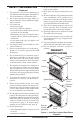
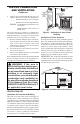
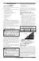
Fireplace Cabinet Hood Screen Log Control Knob Ignitor Button Fireplace Cabinet Hood Logs H I Ignitor Button L O P N Remote Control (Optional) FF 4 PRODUCT IDENTIFICATION O 1. This appliance is only for use with the type of gas indicated on the rating plate. This appliance is not convertible for use with other gases. 2. Do not place propane/LP supply tank(s) inside any structure. Locate propane/LP supply tank(s) outdoors. 3.
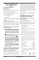
OPTIONAL REMOTE CONTROL ACCESSORIES (For Remote-Ready Models Only) There are four optional remote controls that can be purchased separately for Remote-Ready Models only: • wall switch • hand-held ON/OFF remote • wall thermostat • hand-held thermostat remote See Accessories, page 44. LOCAL CODES Install and use fireplace with care. Follow all local codes. In the absence of local codes, use the latest edition of The National Fuel Gas Code ANSI Z223.1/NFPA 54*.
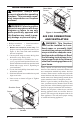
HOOD ASSEMBLY WARNING: Always have screen in place before operating fireplace. This prevents excessive temperatures on fireplace surfaces. Sheet Metal Screws Louver Firebox Top Hood WARNING: Failure to position the parts in accordance with these diagrams or failure to use only parts specifically approved with this fireplace may result in property damage or personal injury. Tools Required: • Phillips screwdriver • slotted screwdriver • 5/16" hex wrench • scissors 1.
AIR FOR COMBUSTION AND VENTILATION Continued PROVIDING ADEQUATE VENTILATION The following are excerpts from National Fuel Gas Code, ANSI Z223.1/NFPA 54, Section 5.3, Air for Combustion and Ventilation. All spaces in homes fall into one of the three following ventilation classifications: 1. Unusually Tight Construction 2. Unconfined Space 3. Confined Space The information on pages 6 through 8 will help you classify your space and provide adequate ventilation.
AIR FOR COMBUSTION AND VENTILATION Continued 4. Compare the maximum Btu/Hr the space can support with the actual amount of Btu/Hr used. _______ Btu/Hr (maximum the space can support) _______ Btu/Hr (actual amount of Btu/Hr used) Example: 35,840 Btu/Hr (maximum the space can support) 40,000 Btu/Hr (actual amount of Btu/Hr used) The space in the above example is a confined space because the actual Btu/Hr used is more than the maximum Btu/Hr the space can support. You must provide additional fresh air.
INSTALLATION NOTICE: This heater is intended for use as supplemental heat. Use this heater along with your primary heating system. Do not install this heater as your primary heat source. If you have a central heating system, you may run system’s circulating blower while using heater. This will help circulate the heat throughout the house. In the event of a power outage, you can use this heater as your primary heat source. WARNING: A qualified service person must install fireplace. Follow all local codes.
INSTALLATION Continued INSTALLATION ITEMS Before installing fireplace, make sure you have the items listed below. • external regulator (supplied by installer, for propane/LP units only) • piping (check local codes) • sealant (resistant to propane/LP gas) • equipment shutoff valve * • test gauge connection* • ground joint union • sediment trap • tee joint • pipe wrench * A CSA design-certified equipment shutoff valve with 1/8” NPT tap is an acceptable alternative to test gauge connection.
INSTALLATION Continued Actual 26" 26 3/4" 14 1/4" Height Front Width Depth Framing 26 7/8" 26 7/8" 15 1/4" 1. Frame in rough opening. Use dimensions shown in Figure 8 for the rough opening. If installing in a corner, use dimensions shown in Figure 10 for the rough opening. The height is 26 7/8" which is the same as the wall opening above. 2. If installing GA3450TA blower accessory, do so at this time. Follow instructions included with blower accessory.
INSTALLATION Continued WARNING: Do not allow noncombustible materials to cover any necessary openings like louvered slots. WARNING: Never modify or cover the louvered slots on the front of the firebox. WARNING: Use only noncombustible mortar or adhesives when overlapping the front facing with noncombustible facing material. Mantel Clearances for Built-In Installation If placing mantel above built-in fireplace, you must meet minimum clearance between mantel shelf and top of fireplace opening.
INSTALLATION Continued 9. Use two 3" wood screws provided and attach base of fireplace to wooden mantel base (see Figure 13). 10. Remove perimeter trim kit and mantel. Be careful not to damage wall or mantel. 11. Cut an access hole in base to run flexible gas line to fireplace (see Figure 13). Make sure to locate access hole so mantel will cover it when installed. Note: You can secure base to floor using wood screws. Countersink screw heads and putty over. 12. Install gas line.
INSTALLATION Continued Installing Blower Accessory CAUTION: Label all wires prior to disconnection when servicing controls. Wiring errors can cause improper and dangerous operation. CAUTION: Verify proper operation after servicing. Note: If you are using a mantel with your fireplace, use the following instructions. If your fireplace is built-in, see For Built-In Installation, page 15. 1.
INSTALLATION Continued For Built-In Installation WARNING: A licensed electrician must connect the wiring harness to electrical supply following all local codes. Electrician must provide a clamp on the box cover to secure the wiring. Wiring should be routed through the bushing in the hole on the outer casing of fireplace. 1. Install snap bushing from blower kit into one hole on rear of remote/blower bracket (see Figure 18).
INSTALLATION Continued CONNECTING TO GAS SUPPLY WARNING: This appliance requires a 45° male flare fitting 5/8"-18 UNF (Unified National Fine Thread) inlet connection and the flexible gas line provided. WARNING: A qualified service person must connect fireplace to gas supply. Follow all local codes. WARNING: Never connect natural gas fireplace to private (non-utility) gas wells. This gas is commonly known as wellhead gas. IMPORTANT: For natural gas, check gas line pressure before connecting fireplace to gas line.
2. Route flexible gas line, included, from fireplace control to equipment shutoff valve through side access holes in outer casing. 3. Apply pipe joint sealant lightly to male threads of gas connector attached to flexible gas line/equipment shutoff valve (see Figure 23). CAUTION: Avoid damage to regulator. Hold gas regulator with wrench when connecting it to gas piping and/or fittings (Thermostat-Controlled Models Only). CAUTION: Avoid damage to gas control.
INSTALLATION Gas Regulator or Gas Control Valve Continued CAUTION: Make sure external regulator has been installed between propane/LP supply and fireplace. See guidelines under Connecting to Gas Supply, page 16. PRESSURE TESTING GAS SUPPLY PIPING SYSTEM Test Pressures In Excess Of 1/2 PSIG (3.5 kPa) 1. Disconnect appliance with its appliance main gas valve (control valve) and equipment shutoff valve from gas supply piping system. Pressures in excess of 1/2 psig will damage heater regulator. 2.
INSTALLATION Continued OPTIONAL WIRELESS HAND-HELD REMOTE CONTROL ACCESSORIES Remote-Ready Models Only ([C]GHRCB Series & [C]GHRCTB Series) I Installing Receiver 1. Disconnect wires from the control valve (see Figure 27) . 2. Locate the battery clip mounted on the back of the receiver (see Figure 28). 3. Slide 9-volt battery (not included) through the clip. 4. Attach the terminal wires to the battery (see Figure 28). 5. Connect wires from remote receiver to control valve as shown in Figure 29. 6.
INSTALLATION Feed wires through rectangular slots Continued 2. Connect one terminal of 25 ft. wire to the “TH” terminal on the control valve. Connect the other terminal to the “THTP” terminal on the control valve. See Figure 32. 3. Route the 25 ft. wire to a convenient location to mount your thermostat (no outside wall). IMPORTANT: The wire may be shortened but must not be lengthened. The thermostat should be mounted 54" above the floor in a location where there is good air circulation.
INSTALLATION Continued IMPORTANT: The wire may be shortened but must not be lengthened. 4. Connect one bare wire end to each of the terminals of the provided wall switch. 5. Install the wall switch and cover in the wall. Rear Brick Liner INSTALLING LOG SET AND SCREEN (Models with One-Piece Screen Only) 1. Remove log packaging material and discard packaging. Gently place log over burner (see Figure 35). Do not allow log to contact flame. If flame contacts log, soot will be created. 2.
INSTALLATION Continued 6. Insert first rod into hole in left side of firebox. Fasten rod to rear hole near center of firebox using black Phillips head screw (see Figure 39). 7. Insert other rod into hole on right side of firebox and fasten rod to front hole near center of firebox using remaining sheet metal screw. Back Center Front Center Hole for Right Screen Assembly Hole for Left Screen Assembly C. Use only your hand to push in or turn the gas control knob. Never use tools.
OPERATING FIREPLACE TO TURN OFF GAS TO APPLIANCE Continued 6. With control knob pressed in, press and release ignitor button. This will light pilot. The pilot is attached to the front burner. If needed, keep pressing ignitor button until pilot lights. Note: If pilot does not stay lit, refer to Troubleshooting, page 30. Also, contact a qualified service person or gas supplier for repairs. Until repairs are made, light pilot with match. To light pilot with match, see Manual Lighting Procedure. 7.
OPERATING FIREPLACE LIGHTING INSTRUCTIONS Continued Note: It is safe to operate fireplace with blower turned off. However, the blower helps distribute heated air from the fireplace. AUTO/OFF/ON Switch Figure 43 - AUTO/OFF/ON Blower Switch REMOTE-READY MODELS FOR YOUR SAFETY READ BEFORE LIGHTING WARNING: If you do not follow these instructions exactly, a fire or explosion may result causing property damage, personal injury or loss of life. A. This appliance has a pilot which must be lighted by hand.
OPERATING FIREPLACE TO TURN OFF GAS TO APPLIANCE Continued 6. With control knob pressed in, press and release ignitor button. This will light pilot. The pilot is attached to the front burner. If needed, keep pressing ignitor button until pilot lights. Note: If pilot does not stay lit, contact a qualified service person or gas supplier for repairs. Until repairs are made, light pilot with match. To light pilot with match, see Manual Lighting Procedure. 7.
OPERATING FIREPLACE Continued Note: The burner may light if hand-held remote was on when selector switch was last turned off. You can now turn the burner on and off with the hand-held remote control unit. IMPORTANT: Do not leave the selector switch in the REMOTE or ON position when the pilot is not lit. This will drain the battery.
OPERATING FIREPLACE Continued 2. The receiver continuously receives signals from the hand-held remote to control the room temperature. If the hand-held remote is misplaced, obstructed, or for any reason cannot transmit to the receiver, the receiver will shut off the fireplace after 8 minutes. Key Pad Lock Feature This feature allows the user to lock/unlock the keypad on the hand-held remote in the MANU or AUTO mode to prevent inadvertent operation (i.e. children operating the hand-held remote control, etc.).
INSPECTING BURNERS CONTINUED BURNER FLAME PATTERN Figure 53 shows a correct burner flame pattern. Figure 54 shows an incorrect burner flame pattern. The incorrect burner flame pattern shows sporadic, irregular flame tipping. The flame should not be dark or have an orange/reddish tinge. Note: When using the fireplace the first time, the flame will be orange for approximately one hour until the log cures.
CLEANING AND MAINTENANCE WIRING DIAGRAM (Remote-Ready Models Only) Continued TPTH TH Gas Control TPTH TP Clean the pilot assembly also. A yellow tip on the pilot flame indicates dust and dirt in the pilot assembly. There is a small pilot air inlet hole about two inches from where the pilot flame comes out of the pilot assembly (see Figures 56 or 57 depending on model). With the unit off, lightly blow air through the air inlet hole. You may blow through a drinking straw if compressed air is not available.
TROUBLESHOOTING WARNING: Turn off and unplug fireplace and let cool before servicing. Only a qualified service person should service and repair fireplace. CAUTION: Never use a wire, needle, or similar object to clean ODS/ pilot. This can damage ODS/pilot unit. Note: All troubleshooting items are listed in order of operation. OBSERVED PROBLEM POSSIBLE CAUSE REMEDY When ignitor button is pressed, there is no spark at ODS/pilot 1. Ignitor electrode not connected to ignitor cable 2.
TROUBLESHOOTING Continued OBSERVED PROBLEM POSSIBLE CAUSE REMEDY ODS/pilot lights but flame goes out when control knob is released 1. C o n t r o l k n o b n o t f u l l y pressed in 2. Control knob not pressed in long enough 1. Press in control knob fully 3. Safety interlock system has been triggered 4. Equipment shutoff valve not fully open 5. Pilot flame not touching thermocouple, which allows thermocouple to cool, causing pilot flame to go out.
TROUBLESHOOTING Continued OBSERVED PROBLEM POSSIBLE CAUSE REMEDY Slight smoke or odor during initial operation 1. Residues from manufacturing processes and log curing 2. Not enough air 1. Problem will stop after a few hours of operation 2. Check burner for dirt and debris. If found, clean burner (see Cleaning and Maintenance, page 28) 3. Replace gas regulator 3. Gas regulator defective Fireplace produces a whistling noise when burner is lit 1.
TROUBLESHOOTING Continued WARNING: If you smell gas • Shut off gas supply. • Do not try to light any appliance. • Do not touch any electrical switch; do not use any phone in your building. • Immediately call your gas supplier from a neighbor’s phone. Follow the gas supplier’s instructions. • If you cannot reach your gas supplier, call the fire department. IMPORTANT: Operating fireplace where impurities in air exist may create odors.
SPECIFICATIONS Thermostat Models: CDCFTP, VDCFTP, FDCFTP Btu/Hr 17/26,000 Type Gas Propane/LP Gas Only Ignition Piezo Manifold Pressure 8" W.C. Inlet Gas Pressure (in. of water) Maximum 14" Minimum* 1" Dimensions, inches (HxWxD) (including hood and screws) 25 7/8 x 26 13/16 x 15 5/16 * For purpose of input adjustment Remote-Ready Models: VDCFRP, FDCFRP, CDCFPR Btu/Hr 17/26,000 Type Gas Propane/LP Gas Only Ignition Piezo Manifold Pressure 8" W.C. Inlet Gas Pressure (in.
REPLACEMENT PARTS SERVICE HINTS Note: Use only original replacement parts. This will protect your warranty coverage for parts replaced under warranty. When Gas Pressure Is Too Low • pilot will not stay lit • burners will have delayed ignition • fireplace will not produce specified heat • for propane/LP units, propane/LP gas supply may be low You may feel your gas pressure is too low. If so, contact your local natural or propane/LP gas supplier.
ILLUSTRATED PARTS BREAKDOWN 19 19 16 16 18 14 12 9 10 9 10 10 10 13 8 11 4 15 16 16 17 5 6 19 16 10 19 11 7 8 16 2 1 16 16 19 3 16 16 19 19 16 16 FIREBOX MODELS CDCFTN, CDCFTP, VDCFTN, VDCFTP, FDCFTN, FDCFTP VDCFRN, VDCFRP, FDCFRN, FDCFRP 36 www.desatech.
PARTS LIST FIREBOX MODELS CDCFTN, CDCFTP, VDCFTN, VDCFTP, FDCFTN, FDCFTP VDCFRN, VDCFRP, FDCFRN, FDCFRP This list contains replaceable parts used in your fireplace. When ordering parts, follow the instructions listed under Replacement Parts on page 35 of this manual. KEY PART NUMBERS NO.
20 38 19 22 10 21 10 23 24 10 9 8 10 10 13 10 www.desatech.
PARTS LIST FIREBOX MODELS CDCFNR, CDCFPR This list contains replaceable parts used in your fireplace. When ordering parts, follow the instructions listed under Replacement Parts on page 35 of this manual. KEY NO.
ILLUSTRATED PARTS BREAKDOWN THERMOSTAT MODELS FDCFTP, FDCFTN, VDCFTP, VDCFTN, CDCFTP AND CDCFTN 9 4 2 1 3 6 5 7 9 8 10 21 9 17 12 11 14 16 13 6 20 15 19 18 40 www.desatech.
PARTS LIST THERMOSTAT MODELS This list contains replaceable parts used in your fireplace. When ordering parts, follow the instructions listed under Replacement Parts on page 35 of this manual. KEY FDCFTP NO.
ILLUSTRATED PARTS BREAKDOWN REMOTE-READY MODELS FDCFRN, FDCFRP, VDCFRN, VDCFRP, CDCFNR, CDCFPR 4 9 2 1 3 6 7 8 5 9 10 9 11 12 14 12 21 20 (FDCFTN/TP, VDCFRN/RP) Natural Gas Only 22 15 9 16 16 H I 15 L O F O F N O P ILOT 18 19 17 13 20 (CDCFNR/PR) 42 www.desatech.
PARTS LIST REMOTE-READY MODELS This list contains replaceable parts used in your fireplace. When ordering parts, follow the instructions listed under Replacement Parts on page 35 of this manual. KEY NO.
ACCESSORIES NOTICE: All accessories may not be available for all fireplace models. Purchase these fireplace accessories from your local dealer. If they can not supply these accessories, call DESA Heating Products at 1-866-672-6040 for referral information. You can also write to the address listed on the back page of this manual. THERMOSTAT-CONTROLLED BLOWER KIT GA3450TA For all models. Provides better heat distribution. Makes fireplace more efficient. Automatically turns off and on as needed.
ACCESSORIES WALL-MOUNT THERMOSTAT SWITCH GWMT1 Continued (Not Shown) For all remote-ready models. The desired comfort setting can be selected on the wall thermostat and the fireplace will automatically cycle from pilot to the heat setting selected. WALL-MOUNT ON/OFF SWITCH GWMS2 (Not Shown) For all remote-ready models. Allows the fireplace to be turned on and off with a wall switch. CORNER MANTEL WITH FULL HEARTH BASE CMA208F Series - Dark Oak CMA209U Series - Unfinished Birch For all models.
NOTES _____________________________________________________ _____________________________________________________ _____________________________________________________ _____________________________________________________ _____________________________________________________ _____________________________________________________ _____________________________________________________ _____________________________________________________ _____________________________________________________ ____________________
NOTES _____________________________________________________ _____________________________________________________ _____________________________________________________ _____________________________________________________ _____________________________________________________ _____________________________________________________ _____________________________________________________ _____________________________________________________ _____________________________________________________ ____________________
2701 Industrial Drive P.O. Box 90004 Bowling Green, KY 42102-9004 www.desatech.com 111244 01 NOT A UPC 111244-01 Rev.