VENT-FREE PROPANE/LP GAS HEATER OWNER’S OPERATION AND INSTALLATION MANUAL ® Model: CGP10T WARNING: If the information in this manual is not followed exactly, a fire or explosion may result causing property damage, personal injury, or loss of life. — Do not store or use gasoline or other flammable vapors and liquids in the vicinity of this or any other appliance. — WHAT TO DO IF YOU SMELL GAS • Do not try to light any appliance. • Do not touch any electrical switch; do not use any phone in your building.
CONTENTS SECTION PAGE Safety Information ......................................................................... 2 Product Identification .................................................................... 4 Local Codes ................................................................................... 4 Unpacking ...................................................................................... 4 Product Features ............................................................................
SAFETY INFORMATION Continued WARNINGS Continued WARNING: Any change to this heater or its controls can be dangerous. 1. This appliance is only for use with the type of gas indicated on the rating plate. This appliance is not convertible for use with other gases. 2. Do not place propane/LP supply tank(s) inside any structure. Locate propane/LP supply tank(s) outdoors. 3.
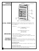
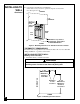
Ignitor Button PRODUCT IDENTIFICATION Control Knob Grill Guard Glass Panel Heater Cabinet Front Panel Figure 1 - Vent-Free Propane/LP Gas Heater LOCAL CODES Install and use heater with care. Follow all local codes. In the absence of local codes, use the latest edition of The National Fuel Gas Code ANSI Z223.1, also known as NFPA 54*. *Available from: American National Standards Institute, Inc. 1430 Broadway New York, NY 10018 National Fire Protection Association, Inc.
AIR FOR COMBUSTION AND VENTILATION WARNING This heater shall not be installed in a confined space unless provisions are provided for adequate combustion and ventilation air. Read the following instructions to insure proper fresh air for this and other fuel-burning appliances in your home. Today’s homes are built more energy efficient than ever. New materials, increased insulation, and new construction methods help reduce heat loss in homes.
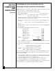
AIR FOR COMBUSTION AND VENTILATION Continued DETERMINING AIR FLOW FOR HEATER LOCATION Determining if You Have a Confined or Unconfined Space Use this worksheet to determine if you have a confined or unconfined space. Space: Includes the room in which you will install heater plus any adjoining rooms with doorless passageways or ventilation grills between the rooms. 1. Determine the volume of the space (length x width x height). Length x Width x Height = ___________________ cu. ft.
AIR FOR COMBUSTION AND VENTILATION Continued WARNING If the area in which the heater may be operated is smaller than that defined as an unconfined space, provide adequate combustion and ventilation air by one of the methods described in the National Fuel Gas Code, ANSI Z223.1, 1992, Section 5.3. VENTILATION AIR Ventilation Air From Inside Building This fresh air would come from an adjoining unconfined space.
AIR FOR COMBUSTION AND VENTILATION Continued Ventilation Air From Outdoors Provide extra fresh air by using ventilation grills or ducts. You must provide two permanent openings: one within 12" of the ceiling and one within 12" of the floor. Connect these items directly to the outdoors or spaces open to the outdoors. These spaces include attics and crawl spaces. Follow the National Fuel Gas Code NFPA 54/ANSI Z223.1, Section 5.
INSTALLING TO WALL NOTICE A qualified service person must install heater. Follow all local codes. CHECK GAS TYPE Use only propane/LP gas. If your gas supply is not propane/LP, do not install heater. Call dealer where you bought heater for proper type heater. INSTALLATION ITEMS Before installing heater, make sure you have the items listed below.
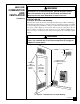
INSTALLING TO WALL For convenience and efficiency, install heater • where there is easy access for operation, inspection, and service • in coldest part of room CEILING Continued 36" Minimum 6" Minimum From Sides Of Heater Right Side Left Side FLOOR 3" Minimum To Top Surface Of Carpeting, Tile Or Other Combustible Material Figure 4 - Mounting Clearances As Viewed From Front of Heater THERMOSTAT SENSING BULB The thermostat sensing bulb is located inside the heater.
INSTALLING TO WALL Continued Installing Two Mounting Screws Note: Wall anchors and mounting screws are in hardware package. The hardware package is provided with heater. Attaching to wall stud method For attaching mounting screw to wall stud 1. Drill hole at marked location using 9/64" drill bit. 2. Insert mounting screw into wall stud. 3. Tighten screw until 1/16" space (thickness of penny) is between screwhead and wall.
INSTALLING TO WALL Continued Placing Heater On Mounting Screws 1. Locate two keyhole slots on back panel of heater (see Figure 9). 2. Place large openings of slots over screwheads. Slide heater down until screws are in small portion of slots. Keyhole Slots Figure 9 - Location Of Keyhole Slots On Back Panel Of Heater Removing Front Panel Of Heater 1. Remove two screws near bottom corners of front panel. 2. Lift straight up on grill guard until it stops. Grill guard will slide up about 1/4". 3.
CONNECTING TO GAS SUPPLY NOTICE A qualified service person must connect heater to gas supply. Follow all local codes. CAUTION Never connect heater directly to the propane/LP supply. This heater requires an external regulator (not supplied). Install the external regulator between the heater and propane/LP supply. The installer must supply an external regulator. The external regulator will reduce incoming gas pressure. You must reduce incoming gas pressure between 11 and 14 inches of water.
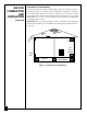
CONNECTING TO GAS SUPPLY IMPORTANT: Hold pressure regulator with wrench when connecting it to gas piping and/or fittings. Continued Pressure Regulator 3/8" NPT Pipe Nipple Heater Cabinet Ground Joint Union Tee Joint Manual Shutoff Valve * Reducer Bushing to 1/8" NPT From External Regulator (11" W.C. to 14" W.C. Pressure) Test Gauge Connection * 1/8" NPT Plug Tap Tee Joint 3" Minimum Pipe Nipple Sediment Trap Cap Figure 13 - Gas Connection * An A.G.A.
CHECKING GAS CONNECTIONS 3. Pressurize supply piping system by either using compressed air or opening propane/LP supply tank valve. 4. Check all joints of gas supply piping system. Apply mixture of liquid soap and water to gas joints. Bubbles forming show a leak. 5. Correct all leaks at once. Continued Test Pressures Equal To or Less Than 1/2 PSIG 1. Close manual shutoff valve (see Figure 14). 2. Pressurize supply piping system by either using compressed air or opening propane/LP supply tank valve. 3.
OPERATING HEATER FOR YOUR SAFETY READ BEFORE LIGHTING WARNING If you do not follow these instructions exactly, a fire or explosion may result causing property damage, personal injury or loss of life. A. This appliance has a pilot which must be lighted by hand. When lighting the pilot, follow these instructions exactly. B. BEFORE LIGHTING smell all around the appliance area for gas. Be sure to smell next to the floor because some gas is heavier than air and will settle on the floor.
OPERATING HEATER 4. Wait five (5) minutes to clear out any gas. Then smell for gas, including near the floor. If you smell gas, STOP! Follow “B” in the safety information at the top of page 16. If you don’t smell gas, go to the next step. Continued 5. Turn control knob counterclockwise to the PILOT position. Press in control knob for five (5) seconds (see Figure 16, page 16). Note: You may be running this heater for the first time after hooking up to gas supply.
OPERATING HEATER Continued TO TURN OFF GAS TO APPLIANCE Shutting Off Heater 1. Turn control knob clockwise to the OFF position. 2. Turn off all electric power to the appliance if service is to be performed. Shutting Off Burner Only (pilot stays lit) to the PILOT position. 1. Turn control knob clockwise THERMOSTAT CONTROL OPERATION The thermostatic control used on these models differs from standard thermostats. Standard thermostats simply turn on and off the burner.
INSPECTING BURNER Check pilot flame pattern and burner flame pattern often. PILOT FLAME PATTERN Figure 18 shows a correct pilot flame pattern. Figure 19 shows an incorrect pilot flame pattern. The incorrect pilot flame is not touching the thermocouple. This will cause the thermocouple to cool. When the thermocouple cools, the heater will shut down.
INSPECTING BURNER Continued BURNER FLAME PATTERN Figure 20 shows a correct burner flame pattern. Figure 21 shows an incorrect burner flame pattern. The incorrect burner flame pattern shows yellow tipping of the flame. It also shows the flame higher than 1/2 the glass panel height. WARNING If yellow tipping occurs, your heater could produce increased levels of carbon monoxide. If burner flame pattern shows yellow tipping, follow instructions at bottom of this page.
CLEANING AND MAINTENANCE WARNING Turn off heater and let cool before cleaning. CAUTION You must keep control areas, burner, and circulating air passageways of heater clean. Inspect these areas of heater before each use. Have heater inspected yearly by a qualified service person. Heater may need more frequent cleaning due to excessive lint from carpeting, bedding material, etc. ODS/PILOT AND BURNER ORIFICE • Use a vacuum cleaner, pressurized air, or small, soft bristled brush to clean.
TROUBLESHOOTING Continued OBSERVED PROBLEM POSSIBLE CAUSE When ignitor button is pressed, there is spark at ODS/pilot but no ignition 1. Gas supply turned off or manual shutoff valve closed 2. Control knob not in PILOT position 3. Control knob not pressed in while in PILOT position 4. Air in gas lines when installed 5. ODS/pilot is clogged 6. Gas regulator setting is not correct ODS/pilot lights but flame goes out when control knob is released 1. Control knob not fully pressed in 2.
TROUBLESHOOTING Continued OBSERVED PROBLEM POSSIBLE CAUSE Burner does not light after ODS/pilot is lit 1. Burner orifice is clogged 2. Burner orifice diameter is too small 3. Inlet gas pressure is too low REMEDY 1. Clean burner orifice (see Cleaning and Maintenance, page 21) or replace burner orifice 2. Replace burner orifice 3. Contact local propane/LP gas company Delayed ignition of burner 1. Manifold pressure is too low 2. Burner orifice is clogged 1. Contact local propane/LP gas company 2.
TROUBLESHOOTING Continued WARNING If you smell gas • Shut off gas supply. • Do not try to light any appliance. • Do not touch any electrical switch; do not use any phone in your building. • Immediately call your gas supplier from a neighbor’s phone. Follow the gas supplier’s instructions. • If you cannot reach your gas supplier, call the fire department. IMPORTANT: Operating heater where impurities in air exist may create odors.
TECHNICAL SERVICE SPECIFICATIONS SERVICE HINTS You may have further questions about installation, operation, or troubleshooting. If so, contact DESA International’s Technical Service Department at 1-800-323-5190. Btu (Variable) Type Gas Ignition Pressure Regulator Setting Inlet Gas Pressure (inches of water) Maximum Minimum Dimensions, Inches (H x W x D) Heater (Including knobs and grill) Carton Weight (pounds) Shipping CGP10T 5,000/10,000 Propane/LP Only Piezo 8" W.C.
1 3 2 6 7 5 9 4 10 8 11 12 26 14 13 15 14 20 16 19 21 25 25 22 23 17 18 10 24 27 ILLUSTRATED PARTS BREAKDOWN CGP10T 26 102922
PARTS LIST This list contains replaceable parts used in your heater. When ordering parts, follow the instructions listed under Replacement Parts on page 25 of this manual. CGP10T KEY NO.
REPLACEMENT PARTS Note: Use only original replacement parts. This will protect your warranty coverage for parts replaced under warranty. Parts Under Warranty Contact authorized dealer from whom you purchased this product. If they cannot supply original replacement part(s), call DESA International’s Technical Service Department at 1-800-323-5190 for referral information.
PARTS CENTRAL These Parts Centrals are privately-owned businesses. They have agreed to support our customer’s needs by providing original replacement parts and accessories. Baltimore Electric 1348 Dixwell Avenue Hamden, CT 06514 1-800-397-7553 203-248-7553 Parts Department Washer Equipment Co. 1715 Main Street Kansas City, MO 64108 KS, MO, AR 816-842-3911 Parts Department Portable Heater Parts 342 N. County Rd. 400 E.
NOTES _________________________________________________________________ _________________________________________________________________ _________________________________________________________________ _________________________________________________________________ _________________________________________________________________ _________________________________________________________________ _________________________________________________________________ ___________________________________________
NOTES _________________________________________________________________ _________________________________________________________________ _________________________________________________________________ _________________________________________________________________ _________________________________________________________________ _________________________________________________________________ _________________________________________________________________ ___________________________________________
WARRANTY INFORMATION KEEP THIS WARRANTY Model Serial No. Date Purchased Always specify model and serial numbers when communicating with the factory. We reserve the right to amend these specifications at any time without notice. The only warranty applicable is our standard written warranty. We make no other warranty, expressed or implied.