
Technical data


227
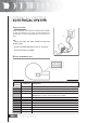
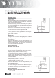
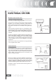
- H.T. coil secondary circuit check
Disconnect the spark plug cap from the H.T. cable and mea-
sure the resistance between the end of the H.T. cable and the
negative terminal of the H.T. coil (see figure).
If the measured values are not as specified, replace the H.T.
coil. To obtain a more accurate diagnosis proceed to verify
the peak voltage using the multimeter adapter.
Electric characteristic
Resistance value
H.T. coil secondary circuit resistance value:
~ 2000 ± 300 ohm
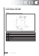
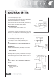
Pick-up
- Disconnect the connector from the central unit and check
that there is a circuit between terminal A (white/green) and
terminal B (yellow/green).
- Set the multimeter onto 200V.
- Crank the engine by operating the starter motor and mea-
sure the voltage produced by the pick-up.
- If the voltage is not as specified, replace the pick-up.
N.B.
THE MULTIMETER MUST BE SET TO MEASURE DIRECT VOL-
TAGE.
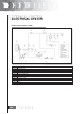
Specific tooling
020409Y Multimeter adapter (Peak voltage measurement)
Electric characteristic
Valore tensione
> 5 Volt
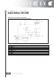
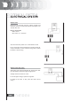
With control unit and H.V. coil normally connected, measure
the voltage of the coil primary during the start up test by the
adapter for peak voltages inserting the positive terminal to
earth and the negative to the positive connector of the coil.
In case of non-conforming values, replace the control unit.
N.B.
THE PLASTIC CAP OF THE POSITIVE TERMINAL OF THE PRI-
MARY OF THE H.V. COIL IS IDENTIFIED BY THE BLACK CO-
LOUR, THE NEGATIVE ONE IS IDENTIFIED BY THE GREEN
COLOUR.
Electric characteristic
Voltage value H.V. coil
> 100 Volt