
Technical data

126
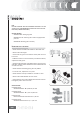
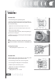
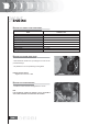
- Install pins and rockers.
- Lubricate the 2 rockers through the top holes.
- Lubricate the 2 connections and insert the camshaft into
the head with the cams opposite the rockers.
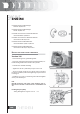
- Insert the retain plate and tighten the 2 screws shown in the
figure at the prescribed torque.
Locking torques (N*m)
Plate screws 4 ÷ 6 Nm
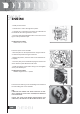
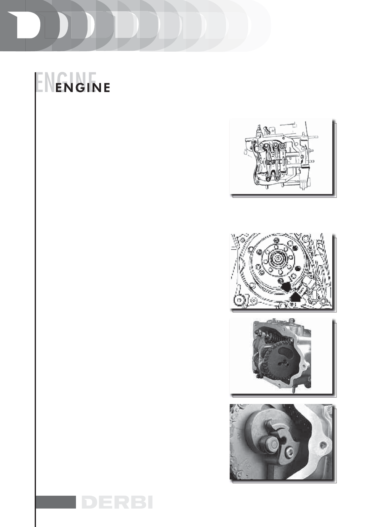
Insert the spacer on the camshaft.
- Place the piston on the top dead centre using the referen-
ces between flywheel and engine crankcase.
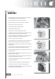
- Keeping this position, insert the chain on the camshaft con-
trol pulley.
- Insert the pulley on the camshaft keeping the reference 4V
at the reference point obtained on the head.
- Install the balance weight with its fixing screw and tighten
at the prescribed torque.
Locking torques (N*m)
Balance weight screw 7 ÷ 8,5 Nm
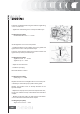
Insert the travel end ring on the valve lifting mass and mount
the valve lifting cam on the camshaft.
N.B.
LUBRICATE WITH GREASE THE TRAVEL END RING TO PRE-
VENT ACCIDENTAL LEAKS WITH CONSEQUENT DROPPING
INTO THE ENGINE.
INSTALL THE VALVE LIFTER RETURN SPRING.DURING THIS
OPERATION, THE SPRING MUST BE LOADED BY ABOUT 180°.