
Technical data


121
N.B.
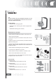
DO NOT CHANGE THE VALVE ASSEMBLY POSITION. FIT THE
VALVES WITH THE REFERENCE COLOUR ON THE HALF-CO-
NES SIDE (LARGER STEP CURLS).
Specific tooling
020306Y Valve sealing ring drift
020382Y Tool for removing valve cotters equipped with
part 012
020382Y011 Bushing (valve remover)
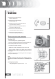
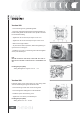
INSPECTING THE CAM SHAFT
- Check that the camshaft ends exhibit no abnormal wear.
- Measure the cam height.
- Check that the groove and relevant retain plate are free
from wear.
- If different values or wear than those prescribed are found,
replace the faulty parts.
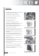
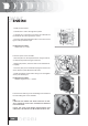
- Check that the automatic valve lifting device cam, the travel
end roller and the rubber abutment on the containment bell
are free from wear.
- Check that the valve lifting spring has not yielded.
- In case of wear, replace the worn parts.
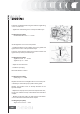
- Check that the rocker pins exhibit no scratches or wear.
- Measure the inside diameter of each rocker.
- Check that the cam contact sliding block and the articula-
ted register plate is free from wear.
Characteristic
Camshaft check:
Standard diameter: Ø 12,000-12,011 mm
Camshaft check:
Standard diameter: Ø 11,977÷11,985 mm
Camshaft check:
Maximum admissible axial clearance
: 0,42 mm
Camshaft check:
Standard axial clearance: 0,11 -0,41 mm
SC G C S