
Technical data


104
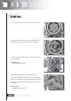
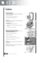
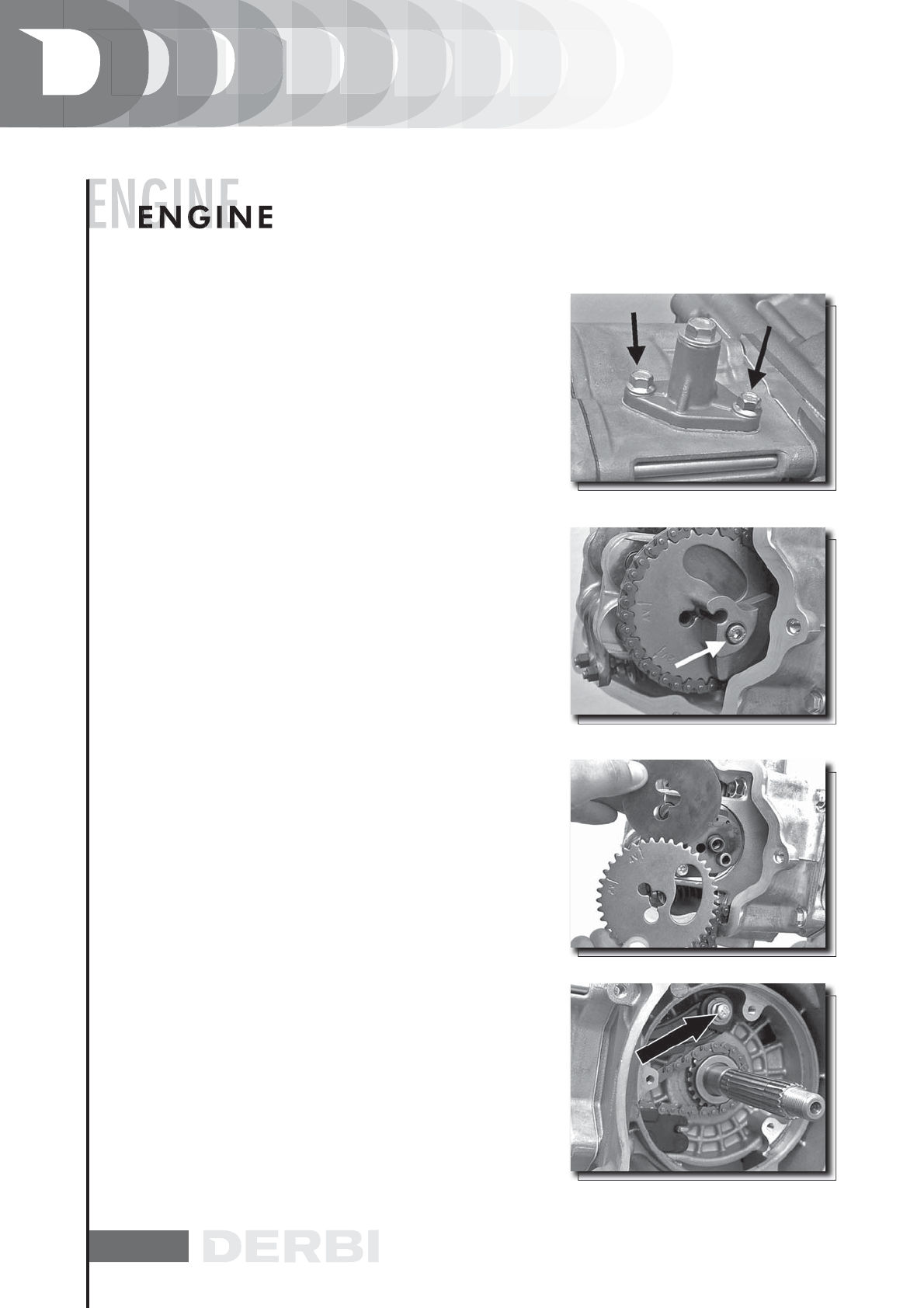
- Loosen the tightener central screw.
- Remove the 2 attachments shown in the figure.
- Remove the tightener with relevant gasket.
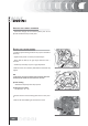
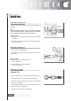
- Remove the inside hexagon screw and the balance weight
shown in the figure.
- Remove the camshaft control pulley and the relevant was-
her.
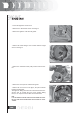
- Remove the control pinion and the timing belt.
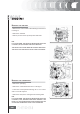
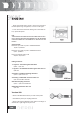
- Remove the screw shown in the figure, the spacer and the
tightener sliding block.
The tightener sliding block must be removed from the trans-
mission side. As regards the lower chain guiding sliding
block, it can only be removed after the head removal.
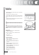
N.B.
IT IS ADVISABLE TO MARK THE CHAIN IN ORDER TO ENSU-
RE THAT THE INITIAL DIRECTION OF ROTATION IS MAIN-
TAINED.