
Assembly Manual

16027-InstructionSheet
INSTALLATION INSTRUCTIONS
HIGH OUTPUT DUAL RAD FAN ASSEMBLY
PART # 16027
KIT CONTENTS
QTY. DESCRIPTION
1 Fan Shroud Assembly
4 Angle Brackets
1 Rubber Fan Shroud Seal
1 180° Thermostat Switch
1 3/8” Radiator Probe
1 Push-in Radiator Probe
1 1 x 1 Foam Pad
1 Retaining Clip
1 190° Thermostat Switch
1 3/8” x 1/8” Adapter Bushing
16 1/4-20 x 3/4” Hex Bolts
16 1/4-20 Nyloc Nuts
QTY. DESCRIPTION
40 1/4” Flat Washers
2 Relay Wire Harness
1 Red Butt Connector
2 Blue #10 Ring Terminals
2 Blue 5/16” Ring Terminals
3 Blue Butt Connectors
2 Blue Female Connectors
4 Blue Wire Tap Connectors
7ft. 14 Gauge Wire
6 4” Wire Ties
4 #10 Sheet Metal Screws
Derale Performance, Los Angeles, CA 800.421.6288 www.derale.com
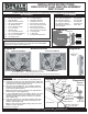
Diagram #1
Engine
Puller Fan
Air Flow
Radiator
Diagram #2
Please read these instructions completely before beginning installation
Flaps open at bottom. Do not
mount with flaps opening at top.
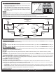
1/4” Bolt
Optional
mounting
Fan Shroud
Radiator Flange
1/4” flat
Washers
Fan Shroud
Angle Bracket
Provided
1/4” Nyloc Nut
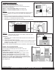
Diagram #4
Cross Flow Radiator
Brackets Provided
Shroud should be mounted tight against radiator to minimize air leaks that would reduce efficiency.
MOUNTING OPTIONS
Diagram #5
MOUNTING
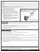
1. Install the Rubber Fan Shroud Seal. (See Diagram #4)
2. Position the electric fan in the desired location. Taking the
Angle Brackets supplied determine the best locations for a
good rigid mount. (See Diagram #2 & 3)
3. Take the four Angle Brackets, 1/4” Hex Bolts, Washers
and Nyloc Nuts provided and attach brackets to the fan
shroud in the desired location.
Flat washers must go between the Angle Bracket
and the shroud. (See Diagram #4)
4. In some applications where the radiator flange is not right
up against the fan shroud, longer bolts can be used to
space Angle Brackets properly. Hardware not included.
(See Diagram #5)
5. Using the remaining 1/4” Hex Bolts, Washers and Nyloc
Nuts provided, mount the Fan Shroud Assembly to the
radiator. (See Diagram #4)
In some cases the radiator flange may have to be
drilled for proper alignment.
Note:
Note:
Diagram #3
Slotted Hole
Down Flow Radiator
Brackets Provided
Flap
5”
Adjustment
Range
1/4” Flat Washer
Fan Shroud
IMPORTANT
This fan assembly is designed for PULLER APPLICATIONS
Engine side of radiator. (See Diagram #1)
ONLY
TOOLS NEEDED
7/16” Open End Wrench
7/16” Socket and Ratchet
5/8” Open End Wrench
11/16” Open End Wrench
3/4” Open End Wrench
Standard Screw Driver or
5/16” Nut Driver
Drill
5/32” Drill Bit
12V Test Light
Wire Stripper
Crimping Tool
Teflon Tape
(Continues on Page 2)
Rubber Fan
Shroud Seal