
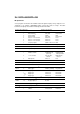
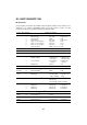
Specifications


496
*1
BHT-BASIC represents the bit order by the exponent of each binary digit in the byte. For
example, bit 0 means LSB; bit 7 means MSB.
*2
The reading confirmation LED is controllable only when the bar code device file is closed.
If the file is opened, the
OUT statement will be ignored.
If you have set the confirmation LED to OFF in the
OPEN "BAR:" statement a user pro-
gram can control the reading confirmation LED although the bar code device file is opened.
*3
Lower four bits (bit 3 to bit 0) in this byte control the contrast level of the LCD in 0000 to
1011 in binary notation or in 0 to 11 in decimal notation. 0 means the lowest contrast; 11
means the highest. Shown below are examples of
OUT statements.
OUT 3,11 ’Contrast is highest
OUT 3,&h0B ’Contrast is highest
*4
The sleep timer feature automatically interrupts program execution if no event takes place
within the specified length of time preset by bit 7 to 0. Shown below are examples of
OUT
statements. Setting 0 to this byte disables the sleep timer feature. (Refer to Chapter 10.)
OUT 6,30 ’3 seconds
OUT 6,0 ’No sleep operation
*5
To activate the wakeup function, set 1 to this bit; to deactivate it, set 0.
*6
To make the TIME$ function return or set the system time, set 0 to this bit; to make the
TIME$ function return or set the wakeup time, set 1.
Execution of the
TIME$ function after selection of the wakeup time will automatically reset
this bit to zero.
*7
The BHT-6000/BHT6500 may display the system status on the bottom line of the LCD. To
display the system status, set 1 to this port; to erase it, set 0. For the system status indica-
tion, refer to Chapter 7, Subsection 7.1.7.
*8
This byte sets the re-read prevention enabled time length in units of 100 ms. Specification
of zero (0) permanently enables the re-read prevention so that the BHT-6000/BHT6500
does not read same bar codes in succession. The default is 10 (1 second).
*9
An 8-bit binary pattern (bits 7 to 0) on the output ports 10h to 24Fh (which are stored in the
VRAM) represents a basic dot pattern column of the LCD. Bit value 1 means a black dot.
The port number gives the dot column address.
If you send graphic data to the VRAM area (assigned to the bottom line of the LCD) by
using the OUT statement when the system status is displayed on the LCD, the sent data
will be written into that VRAM area but cannot be displayed on the bottom line of the LCD.
*10
Refer to Appendix H, "[ 3 ] Program file named APLINT.PD3."
*11
If the backlight function is activated with the OUT statement, the specification by the KEY
statement will be ignored. For details, refer to Chapter 13.
If you set 0 to the ON-duration (6021h), the backlight will not come on; if you set 255, it will
be kept on.
*12
You can set the held-down time of the power key required for powering off the BHT-6000/
BHT6500. The setting range is from 0.1 to 25.5 seconds in increments of 0.1 second. The
default is 5 (0.5 second).