
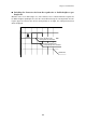
Specifications


112
7.4 Controlling and Monitoring the I/Os
7.4.1 Controlling by the OUT Statement
The OUT statement can control the input and output devices (I/Os) listed in Appendix D, I/O
Ports." The table below lists some examples.
7.4.2 Monitoring by the INP Function
The INP function monitors the input and output devices (I/Os) listed in Appendix D, "I/O Ports."
The table below lists some examples.
* The INP function can monitor the trigger switch status only when the trigger
switch function is assigned to any of the magic keys.
OUT Statement
I/O Devices
OUT 1,&h02
OUT 1,&h01
OUT 1,&h00
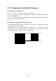
Turns on the indicator LED in green.
Turns on the indicator LED in red.
Turns off the indicator LED.
OUT 3,&hXX (XX: 00 to 07) Sets the LCD contrast.
OUT 4,&h00
OUT 4,&h01
Sets the Japanese message version.
Sets the English message version.
OUT 6,&hXX (XX: 00 to FF) Sets the sleep timer.
INP Function
I/O Devices Value Meaning
INP(0) AND &h01
Keyboard buffer & touch
key buffer status
1
0
Data present
No data
INP(0) AND &h02
Bar-code buffer status 1
0
Data present
No data
INP(0) AND &h04
Trigger switch status* 1
0
Being pressed
Being released
INP(0) AND &h08
Receive buffer status 1
0
Data present
No data
INP(0) AND &h10
TIMEA function 1 Set to 0
INP(0) AND &h20
TIMEB function 1 Set to 0
INP(0) AND &h40
TIMEC function 1 Set to 0