
User Guide


Table Of Contents
- SAFETY PRECAUTIONS
- NOTE ON USE
- SAFETY INSTRUCTIONS
- INTRODUCTION
- TABLE OF CONTENTS
- ACCESSORIES
- 1. BEFORE USING
- 2. CAUTIONS ON INSTALLATION
- 3. CAUTIONS ON HANDLING
- 4. FEATURES
- 5. CONNECTIONS
- 6. PART NAMES AND FUNCTIONS
- 7. SETTING UP THE SYSTEM
- 8. REMOTE CONTROL UNIT
- 9. OPERATION
- 10. SURROUND
- 11. DSP SURROUND SIMULATION
- 12. LISTENING TO THE RADIO
- 13. LAST FUNCTION MEMORY
- 14. INITIALIZATION OF THE MICROPROCESSOR
- 15. TROUBLESHOOTING
- 16. ADDITIONAL INFORMATION
- 17. SPECIFICATIONS
7
IN
VIDEO
R
L
R OUT IN
AUDIO
VIDEO
OUT IN
LRL
R
L
R
L
R OUT IN
AUDIO
VIDEO
OUT IN
LRL
R
L
R
L
R OUT
VIDEO
OUT
L
AUDIO
L
R
R OUT
VIDEO
OUT
L
AUDIO
L
R
R
L
R
L
R
L
R
L
RL
B
B
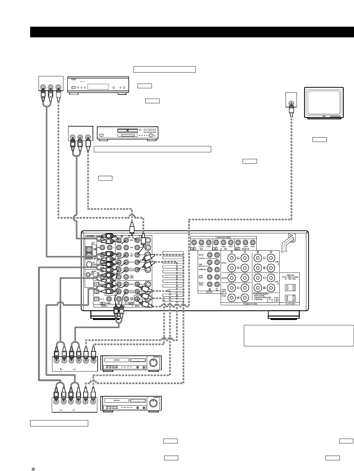
Connecting video components
• To connect the video signal, connect using a 75 Ω/ohms video signal cable cord. Using an improper cable can result in a drop in video quality.
• When making connections, also refer to the operating instructions of the other components.
TV or DBS tuner
Connecting a TV/DBS tuner
TV/DBS
• Connect the TV’s or DBS tuner’s video output jack (VIDEO OUTPUT) to the
(yellow) TV/DBS IN jack using a 75 Ω/ohms video coaxial pin plug
cord.
• Connect the TV’s or DBS tuner’s audio output jacks (AUDIO OUTPUT) to
the TV/DBS IN jacks using pin plug cords.
AUDIO
VIDEO
DVD player or video disc player (VDP), etc.
Connecting a DVD player or a video disc player (VDP)
DVD
• Connect the video disc player’s video output jack (VIDEO OUTPUT) to the (yellow) DVD IN
jack using a 75 Ω/ohms video coaxial pin plug cord.
• Connect the video disc player’s analog audio output jacks (ANALOG AUDIO OUTPUT) to the
DVD IN jacks using pin plug cords.
• A VDP can be connected to the VDP jacks in the same way.
• It is also possible to connect a video disc player, DVD player, video camcorder, game machine, etc.,
to the VCR-2/V.AUX jacks.
AUDIO
VIDEO
Monitor TV
MONITOR OUT
• Connect the TV’s video
input jack (VIDEO INPUT) to
the MONITOR
OUT jack using a 75
Ω/ohms video coaxial pin
plug cord.
VIDEO
Note on connecting the digital input jacks
• Only audio signals are input to the digital input jacks.
For details, see page 6.
Video deck 2
Video deck 1
Connecting a video decks
• There are two sets of video deck (VCR) jacks, so two video decks can be connected for simultaneous recording or video copying.
Video input/output connections:
• Connect the video deck’s video output jack (VIDEO OUT) to the (yellow) VCR-1 IN jack, and the video deck’s video input jack (VIDEO IN) to the
(yellow) VCR-1 OUT jack using 75 Ω/ohms video coaxial pin plug cords.
Connecting the audio output jacks
• Connect the video deck’s audio output jacks (AUDIO OUT) to the VCR-1 IN jacks, and the video deck’s audio input jacks (AUDIO IN) to the VCR-1
OUT jacks using pin plug cords.
Connect the second video deck to the VCR-2/V.AUX jacks in the same way.
AUDIOAUDIO
VIDEOVIDEO