7-06 RD20010,Rev 6 1
Introduction Thank you for purchasing a Demco Kar-Kaddy. We feel you have made a wise choice and hope you are completely satisfied with your new piece of equipment. GENERAL INFORMATION 3. When placing a parts order, refer to this manual for proper part numbers and place order by PART NO. and DESCRIPTION. 1. Unless otherwise specified, high-strength (grade 5) (3 radial-line head markings) hex head bolts are used throughout assembly of this piece of equipment. 2.
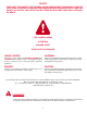
SAFETY TAKE NOTE! THIS SAFETY ALERT SYMBOL FOUND THROUGHOUT THIS MANUAL IS USED TO CALL YOUR ATTENTION TO INSTRUCTIONS INVOLVING YOUR PERSONAL SAFETY AND THE SAFETY OF OTHERS. FAILURE TO FOLLOW THESE INSTRUCTIONS CAN RESULT IN INJURY OR DEATH. THIS SYMBOL MEANS ATTENTION BECOME ALERT YOUR SAFETY IS INVOLVED! SIGNAL WORDS WARNING: Note the use of the signal words DANGER, WARNING and CAUTION with the safety messages.
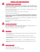
SAFETY...YOU CAN LIVE WITH IT EQUIPMENT SAFETY GUIDELINES Every year many accidents occur which could have been avoided by a few seconds of thought and a more careful approach to handling equipment. You, the operator, can avoid many accidents by observing the following precautions in this section. To avoid personal injury, study the following precautions and insist those working with you, or you yourself, follow them.
• Replacement parts that displayed a safety sign should also display current sign. • Safety signs are available from your distributor, dealer parts department, or factory. How to install safety signs: • Be sure installation surface is clean and dry. • Decide on exact position before you remove backing paper. • Remove smallest portion of split backing paper. • Align decal over specified area and carefully press small portion with exposed sticky backing in place.
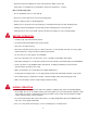
• Secure emergency brake actuator cable to mounting loop on towing vehicle. • Beware of bystanders, PARTICULARLY CHILDREN! Always look around to make sure it is safe to start engine of towing vehicle or move unit. This is particularly important with higher noise levels, as you may not hear people shouting. • NO PASSENGERS ALLOWED- Do not carry passengers anywhere on or in towed unit. • When halting operation, even periodically, set towing vehicle parking brake, shut off engine, and remove ignition key.
• Local laws should be checked for all highway lighting and marking requirements. • Plan your route to avoid heavy traffic. • Be a safe and courteous driver. Always yield to oncoming traffic in all situations, including narrow bridges, intersections, etc. • Watch for obstructions overhead and to both sides while transporting. • Operate with maximum visibility at all times. Make allowances for increased length and weight of KK460SS when making turns and stopping.
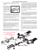
Decal Location PINCH POINT REV 0 A. DD21018 D. DD21018 DD21017 WARNING Read following information before hooking up, loading, using, unloading or unhooking Kar Kaddy to prevent property damage, serious injury, or death. QTY. 4 Loading Towed VehicleE 1. Assure towing vehicle and Kar Kaddy are straight, on level ground, and properly hooked up before loading towed vehicle. IMPORTANT DO’S & DON’TS Read towing instructions in towed vehicle C owners manual. Use 2” 5000 lb.
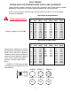
BOLT TORQUE TORQUE DATA FOR STANDARD NUTS, BOLTS, AND CAPSCREWS. Tighten all bolts to torques specified in chart unless otherwise noted. Check tightness of bolts periodically, using bolt chart as guide. Replace hardware with same grade bolt. NOTE: Unless otherwise specified, high-strength Grade 5 hex bolts are used throughout assembly of equipment. Bolt Torque for Standard bolts * Torque Specifications “A” Torque Lug Nuts to 120 FT/LBS 1/4” 5/16” 3/8” 7/16” 1/2” 9/16” 5/8” 3/4” 7/8” 1” GRADE 2 lb-ft (N.
Tongue and Ramp Assembly Instructions 1. Place the main frame (#1) on blocks or some other sturdy support so that the frame rests approximately 8" - 10" off the ground. of each bracing strut to the trailer frame as shown using 1/ 2" x 1-1/2" grade 5 bolt (#6), flatwasher (#7), pivot bushing (#8) and locknut (#9). Hold up the front end (the end with the smaller hole) of each bracing strut to the tongue and secure with two 5/8" x 1-1/4" epoxied hex head bolts (#10) and nut plate (#14).
Fender Assembly Instructions 3. On the left side, plug in bullet plugs with white to white, black to brown and yellow to red. On the right side, plug white to white, black to brown and green to red. 1. Install fender with fender backup plate (#1) and three 3/8” x 1-1/2” bolts (#2). Put 3/8” nylon lock nuts (#3) inside of fender and tighten. 4. With a pliers, install two wire clamps on fender. From rear of fender lip, install one clamp at 5-1/2” and one at 8”. 2.
Wiring Diagram 1 2 PARTS LIST REF. NO. PART NO. QTY. 1. 2. 3. 11590 11591 01863 1 1 1 DESCRIPTION Tongue Wiring Harness Main Frame Wiring Harness Rubber Grommet (not shown) Please order replacement parts by PART NO. and DESCRIPTION. TESTING LIGHTS BEFORE USE 1. Make sure that the WHITE ground wire is connected to the frame of both the Kar Kaddy and the towing vehicle. 2.
Tongue folding and storage NOTE: Tow Dolly must be empty and unhooked to perform any and all of these steps. Do not attempt while tow dolly is loaded or hooked up. 1. Pull retainer clip from bottom of tongue locking pin. Lift locking pin out of tongue pivot. 2. With tongue wheel jack turned to its lowest position, push/pull tongue to the left. 3. Push/pull tongue until it comes to a stop by the left fender. It is recommended to place lock pin and retainer clip back in tongue pivot for storage.
Folding Ramp Lock NOTE: Tow Dolly must be empty and unhooked to perform any and all of these steps. Do not attempt while tow dolly is loaded or hooked up. 1. Locate ramp locks at inside center of ramps. 2. Pull ramp lock straight out as far as it will go. 3. Lift ramp lock up as far as it will go and allow lock to slide in until it stops. 4. If lock has been pulled and lifted properly the ramp lock will extend out from it’s holder. This will mean that the ramp is unlocked and ramp may be folded up.
Folding Ramp NOTE: Tow Dolly must be empty and unhooked to perform any and all of these steps. Do not attempt while tow dolly is loaded or hooked up. 1. Pull ramp back as far as it will go. Bolt must be past notch before attempting the next step. 2. Lift ramp until it is past center and resting on it stops. IMPORTANT: When taking this tow dolly out of storage it is very important to check all pins and retainers for damage. If damage is found replace. Do not use damaged pins or retainers.
! WARNING: FAILURE TO FOLLOW THESE INSTRUCTIONS CAN RESULT IN LOSS OF TOWING VEHICLE CONTROL, SEPARATION OF THE TOW DOLLY FROM THE TOWING VEHICLE, SEPARATION OF THE TOWED VEHICLE FROM THE TOW DOLLY, CAUSING SEVERE PERSONAL INJURY, DEATH, OR PROPERTY DAMAGE. ! SAFETY Rear Wheel Drive: Disconnect the towed vehicle driveshaft for rear wheel drive vehicles with automatic transmission. For manual transmission: Consult your vehicle owners manual for towing suitability with the drive shaft connected.
LOADING INSTRUCTIONS . Step 1. Secure ball coupler to 2" (5,000 lb. capacity) towing vehicle ball only. Make sure that the hitch and the hitch ball are in good condition and not rusted, loose or stripped. Recommended ball height is 18" to the top of the ball. Make sure hitch is locked down and secured with safety clip. Criss-cross safety chains under tongue and secure to towing vehicle frame. Step 4.
Step 7. Drive vehicle onto the platform - front forward - until tires touch the wheel stops at the front of each side of the platform and the platform tilts to a flat position. Make sure the car is centered on the platform. Towed vehicle tires must fit in wheel troughs without overhanging sides. Engage towed vehicle parking brake. Shift loaded car into "park" and lock steering wheel with front tires in a straight position.
A B Step 13. TO UNLOAD towed vehicle. Never unhook tow dolly coupler from towing vehicle, before unloading todolly. Make sure that platform and vehicle are straight. Reinstall driveshaft. Ensure that towed vehicle parking brake is fully engaged, then unhook the towed vehicle safety chains, and release the tie-down straps. NOTE: Tie down straps must be "quick -released" by grasping ratchet pawl (A) and ratchet handle (B) simultaneously and pushing down sharply.
KAR-KADDY TOE-IN ADJUSTMENT BA CK LOCKING CLAMP FRONT MEASUREMENT (1/32" to 1/16" less than back measurement) ME AS UR EM EN T 12" 12" CL 18" nd ou r G MEASURING THE TOE-IN TOE-IN ADJUSTMENT Have the tongue in a "hooked-up” position with the ball coupler 18" off the ground. Jack up the axle just enough to allow you to take the wheels off and put blocks under the axle. Take the wheels off. 1. Put a mark on each side of the locking clamp on the tie rod. Find two 24" long bars.
MODEL DA91 ACTUATOR PARTS BREAKDOWN 13 8 8 23 17 **12 **10 **16 5398 Master Cylinder Repair Kit (gasket included) 14 14 15 15 18 25 9 26 not included 6 20 9 7 22 28 21 4 5 19 5696 Coupler Repair Kit 24 2 9 19 28 2 27 1 3 2” Lever Lock Coupler RATED AT 6000# BLEEDING THE SYSTEM The first requirement for safe, sure hydraulic braking is the use of quality brake fluid. Use only DOT-3 or DOT-4 brake fluid from a sealed container.
10" SELF-ADJUSTING BRAKE CLUSTER and DRUM PARTS BREAKDOWN 4 4 5 5 7 16 1 6 16 3 2 2 8 11 13 10 12 3 19 10 9 17 18 17 15 14 17 BRAKE CLUSTER PARTS LIST REF. PART NO. NO. QTY. SB24429M SB24428M 1. SB23871 1 2. SB9254 2 3. SB10954 1 4. 04305 2 5. 05424 2 6. SB9776 1 SB9777 1 7. 05431 1 8. SB9783 1 9. SB24047 1 SB24048 1 10. SB10958 2 11. SB10961-95 1 12. SB23937 1 13. SB23936 1 14. SB23724 1 15. 05415-95 1 05414-95 1 16. SB10959 2 17. SB9789 4 18. 05983 2 19.
SURGE BRAKES PARTS BREAKDOWN 12 13 11 11 10 8 9 17 5 4 7 3 4 10 11 6 11 13 1 2 18 16 14 15 Model DA91 Brake Actuator SURGE BRAKES FIELD SETUP PARTS LIST SURGE BRAKES FACTORY SETUP PARTS LIST REF. NO. PART NO. QTY. DESCRIPTION REF. NO. PART NO. QTY. 1. 2. 3. 4. 5. 6. 7. 8. 9. 10. 11. 12. 13. 14. -15. 16. 17. 18.
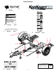
KK460SS PARTS BREAKDOWN 2 1 4 5 41 6 46 45 7 41 46 43 13 9 40 53 12 10 39 11 53 26 28 29 60 27 57 58 19 20 56 22 36 38 52 26 21 37 50 23 52 24 25 48 55 22 75 54 6 47 23 19 71 21 37 49 24 26 19 51 59 58 76 56 62 21 61 32 32 63 60 65 64 24 21 20
REF. NO. PART NO. QTY. 1. 03528 2 2. 5737 1 3. 5736 1 4. 04424-95 2 5. 00914 6 6. 02592 18 7. 04165-80 1 8. 04166-80 1 9. 01732 4 10. 11588 2 REF. NO. DESCRIPTION 33 35 32 31 34 21 22 19 26 34 30 6 21 22 6 42 44 34 21 22 15 18 19 16 17 14 3 8 66 73 QTY. DESCRIPTION 11. 01731 4 1-1/4" Dust Cap 12. 05587 2 1" I.D.x 14 GA Narrow Rim Machine Washer 13. 11566-80 1 Right Drop Axle Mount 14. 11550-80 1 Left Drop Axle Mount 15. 11551 2 King Pin Retainer Bolt 16.
WINCH ASSEMBLY 5 1 Left Winch 5432 (Shown) Right Winch 5433 2 3 11 7 4 18 1. 2. 3. 4. 5. 6. 7. 8. 9. 10. 11. 12. 13. 14. 15. 16. 17. 18.
RAMP LATCH ASSEMBLY REF. NO. 1. 2. 3. 4. 5. 6. 7. 8. 9. 5 1 2 QTY. 5763 11622-95 00007 00004 00059 11570-95 11623-95 03499 02384 11621 1 2 1 1 1 1 1 1 1 DESCRIPTION Ramp Latch Kit 5/16"-18 UNC Latch Rod 5/16"-18 UNC Hex Nut 5/16" Flatwasher 3/8” Flatwasher Latch Block Threaded Bushing Latch Spring - Stainless Steel 1/2” Narrow Machine Washer Handle/Knob Please order replacement parts by PART NO. and DESCRIPTION. 6 4 PART NO. 2 3 7 8 9 LICENSE PLATE BRACKET ASSEMBLY le) ilab a v ta (no REF.
Fender Assembly 8 6 1 7 9 18 2 5 2 2 12 2 14 2 3 19 17 11 4 10 13 16 15 PARTS LIST REF. NO. PART NO. QTY. 1. 2. 3. 4. 5. 6. 7. 8. 9. 10. 11. 12. 13. 14. 15. 16. 17. 18. 19.
OPTIONAL SPARE TIRE and MOUNT PARTS BREAKDOWN Drive in stud here for tire with rim #11574 (115mm bolt circle). PARTS LIST 1 4 6 5734 1 Optional Spare Tire and Rim 1. 2. N/A 11574 1 1 ST205/75R 14"x"C" ROWL RadialTire 1 1 1 2 2 2 4 Spare Tire Mounting Bracket Spare Tire Bracket Stud Bolt (12mm x 1.5) Wheel Nut (12mm) Chrome 3/8"-16UNC Square U-Bolt 3/8" Flatwasher 3/8"-16UNC Nylon Insert Locknut RKSTM 3. 02193-30 4. 02917 5. 02933 6. 02759 7. 00059 8.
OPTIONAL LIGHT BAR PARTS BREAKDOWN 7 6 8 1 LIGHT BAR PARTS LIST REF. PART NO. NO. QTY. 1. 2. 3. 4. 5. 6. 7. 8. 9. 10. 11. 12. 13. 14. 15. 16. RKLB 01772 01857 01773 01886 02385-50 02386.
DEMCO PRODUCTS - KAR KADDY ORIGINAL PURCHASER’S LIMITED WARRANTY 1. Extent and Duration of this Warranty: Your Demco Kar Kaddy is warranted to be free from defects in materials and workmanship under normal use and service for a period of one year after date of purchase by the original (first) retail owner, or until it is resold or transferred by the original owner.
NOTES: 32
Warranty Registration Dethmers Manufacturing Company 4010 320th Street • Box 189 • Boyden, Iowa 51234 Toll Free 800-54DEMCO (800-543-3626) • FAX 800-845-6420 www.demco-products.
Postage Dethmers Manufacturing Company 4010 320th Street, Box 189 Boyden, Iowa 51234 34
NOTES: 35
DETHMERS MFG. COMPANY P.O. BOX 189 4010 320th St., BOYDEN, IA. 51234 PH: (712) 725-2311 FAX: (800) 845-6420 TOLL FREE: 1-800-54DEMCO (1-800-543-3626) www.demco-products.