
User's Manual
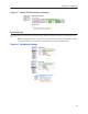
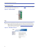
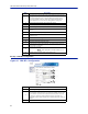
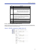
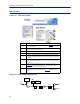
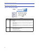
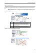
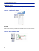
Table Of Contents
- Safety Precautions
- About This Manual
- Table of Contents
- Chapter 1 Introduction
- Chapter 2 System Description
- Chapter 3 Installation guidelines
- Chapter 4 DAS Software Configuration
- Chapter 5 Commissioning
- Chapter 6 RF Commissioning
- Chapter 7 Model Identification

FiberDistributedAntennaSystem(FiberDAS)
85
FOR Opto Status
Figure 95 FOR Opto Status
1
2
3
4
5
6
7
8
Figure 96 FOR Downlink Schematic
CURRENT
SENSOR
ETHERNET
MODEM
OPTO IN
RX-LVL
RF OUT 1
RF OUT 2
PHOTO
DETECTOR
STEP ATT STEP ATT
1
Item Description
1
OpticalpowerreceivedfromtheFOI.Seeitem1in
Figure96
for
measurementlocation.
2
UplinksignalbeingfedintotheFORuplinklasercircuit.Seeitem2in
Figure97
formeasurementlocation.
3LasercurrentfortheRemoteUnitFOR.Shouldbelessthan50mA.
4TemperatureoftheRemoteUnitFORboard.
5
TotalgainoftheFORinthedownlink.NotethatRFOut1and2arewide
band(FMto2600MHz)thatfeedbandspecificRFamplifiersinthefollowing
VGA
stage.
6
TotalgainoftheFORintheuplinkpath.NotethatRFIn1andIn2arewide
band(FMto2600MHz)thataresignalsfromtheuplinkfrequencyspecific
amplifiers.
7
CalculateddownlinksignalbeingreceivedfromtheFOI.Seeitem1in
Figure96
formeasurementlocation.Takesintoconsiderationoptical
wavelengthandtemperaturecompensation.
8
CalculateduplinksignalbeingtransmittedtotheFOI(FORinputfromVGA+
FORuplinkgain/attenuation).Seeitem3in
Figure97
formeasurement
location.