
User's Manual
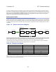
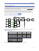
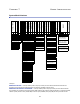
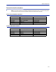
Table Of Contents
- Safety Precautions
- About This Manual
- Table of Contents
- Chapter 1 Introduction
- Chapter 2 System Description
- Chapter 3 Installation guidelines
- Chapter 4 DAS Software Configuration
- Chapter 5 Commissioning
- Chapter 6 RF Commissioning
- Chapter 7 Model Identification

FiberDistributedAntennaSystem(FiberDAS)
111
Whatweseehereisthatifwesetthesystemupinthisfashionwewilldesensitizethebasestationwithabout5,5
dB.ThiscanbeokayifthebasestationcoverageisonlythroughtheFiber‐DASsystembutifthebasestationisalso
beingusedforoutdoorco
verageitisnotgood.Weneedtochangethenetgaintoreflectthis.Ingeneralweshould
lowerthegainsothatwedesensitizetheBTSonlyabout3dB.Thisvalueisagoodcompromiseandsimilartoadding
asecondantennatothesamereceiverport(whichiskindof
whatwearedoingwiththeFiber‐DAS).
Herearethene
wvalues:
Table 70
Chain NF Gain Noise Load
RU1
RU2
RU3
RU4
BaseStati
on
Fib
er‐DASNo
iseLoad
TotalNoisein
toBTS
Adjusted Noise Load
Asyoucanseeweshouldsetthesystemupwithanetgainofabout‐5dB.Goingbacktothesettingswehadbefore
whichwas:
Table 71 Example Link Budget
Unit/Component Gain/Loss (dB) Accumulated Gain/Loss (dB)
RemoteUnit(RU)
Fib
er‐OpticCable
FO
I
ICU
BIU
Coupler
Weonlynee
dtoch
angetheBIUsettingusingtheattenuatorsintheBIUtolowerthegainwith5dB.Thiswill
accomplishwhatweneedtodoandtheuplinkshould thenbecommissioned.
2.8 -5.5 -2.2
3.2 -5.5 -1.8
3.8 -5.5 -1.2
2.6 -5.5 -2.4
Sum of Noise Load 4.1
4.0
4.1
7.1
Desensitization -3.1
40 40
-10 30
20 50
-35 15
015
-15 0