
User's Manual


DELTANODE USER MANUAL
©DeltaNode Solutions 2015
11
Revision 15-01
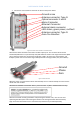
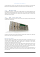
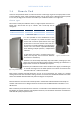
OPTO IN/OUT
This is the receptacle for the optical fiber. The illustration shows the module
with built in WDM (combined Rx/Tx).
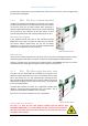
UL OUT 1/2
These are the RF ports that normally are patched to the POI for
interconnecting and then further on to the BIU.
DL IN 1/2
These are the RF ports where the signal in the DL from the POI is patched into
the FOI for conversion to laser light and further to the RU.
TP UL/DL
These are test ports that can be used to check the signal levels or noise in the
DAS- system.
Single mode fiber
Angled connectors
Optical loss < 15 dBo
Every time a fiber is disconnected and re-connected care should be taken to avoid dust to settle on
the connector or in the receptacle. Clean with a dry fiber cleaning tool before reconnecting the fiber
at all times. A single speck of dust can impact the transmission severely. Do not touch the fiber ends
with your fingers. That will leave grease on the connectors and may cause severe problems.
Functional description
The output power of the laser is calibrated and tuned to 3 000 µW.
The FOI is powered from the rack backplane and communicates with Ethernet with the other
modules in the Master Unit.
The unit contains adjustable attenuators.
This interface is designed to work with SC-APC connectors (7° angled
physical connector) and single mode fibers only. All connectors between
the master unit and the remote unit should be of angled type, otherwise
problems with reflections will arise which may cause severe problems in
the DAS- system.
Ports of the FOI
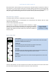
There are also two LED´s on the unit which can be used for visual check of the current status of the
FOI. Green led for operation status and the red one for current alarm status.