
User's Manual
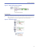
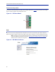
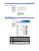
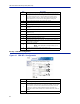
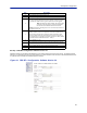
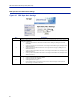
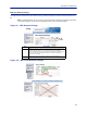
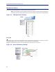
Table Of Contents
- Safety Precautions
- About This Manual
- Table of Contents
- Chapter 1 Introduction
- Chapter 2 System Description
- Chapter 3 Installation guidelines
- Chapter 4 DAS Software Configuration
- Chapter 5 Commissioning
- Chapter 6 RF Commissioning
- Chapter 7 Model Identification

DASSoftwareConfiguration
84
RF Strip 1 XXX MHz Configuration Software Version 3.9
Softwarerelease3.9in
troducessettableReturnLossmeasurementsandcontroloveralarms.Thedefaultinterval
settingis“0”indicatingthereturnlossalarmfeatureisturnedoff.Returnlossalarmsareoftendisabledwhenthere
isapassiveantennanetworkinstalledbeyondtheremote.
Figure 94 FOR RF 1 Configuration, Software Version 3.9
4 Turnsdownlinklowpoweralarmonoroff.
5UplinkgainsettingforRFpathunderreview.
6
UplinkALCsettingforRFpathunderreview .Thisisthethresholdatwhich
thesystemwillstartreducingfurthergaintopreventincreasesinuplinkRF
totheFOI.After10dBdecreaseingainanuplinkalarmwill
betriggered
Note: Shouldbeleft
afactorydefault.OnlychangeifFOR
uplinkgainischanged.IfgainisincreasedonFORuplink
thenthesamevalueshouldbedecreasedontheALC.
Example:ChangingtheULFORgainfrom12to17wouldrequireALCtobe
changedfrom‐13to‐18.
7
HardwareAL
C
offsetmeasuredintenthsofadB.Defaultsettingof60
(6dBm)shouldbeusedformostapplications.Shouldthesoftwarenotbe
abletoreduceuplinkgainfastenoughaftertheALCthresholdhasbeen
exceed,hardwareattenuationwillbeaddedtoprotecttheuplinkpath.In
theexa
mpleabov
e,thehardwareattenuationwilltriggerat‐7dBm(‐13dBm
ALCthresholdminus6dBmHWALCoffset=‐7dBm)
8 TurnsuplinkRFonoroff.
9
Setsuplinktesttonefrequency.Mustbewithinuplinkfrequencylimitsof
theRFmodule.
10 Turnsonuplinktesttone.Testtonetimesoutafter60minut
es.
11
RetrievescurrentFORsettingsfromsystem.
Item Description