
User's Manual
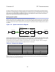
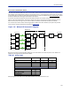
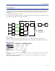
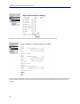
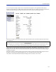
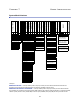

Table Of Contents
- Safety Precautions
- About This Manual
- Table of Contents
- Chapter 1 Introduction
- Chapter 2 System Description
- Chapter 3 Installation guidelines
- Chapter 4 DAS Software Configuration
- Chapter 5 Commissioning
- Chapter 6 RF Commissioning
- Chapter 7 Model Identification

115
Chapter 7 Model Identification
System Model Numbers
Examples :
DDR4-GC0-PA1-AD — 4band
,33dBmpoweroutputperband,Fullband700combinedwithCell850non
duplexed,PCSco
mbinedwithAWSduplexed,ACpowered,7/1 6 DIN,1310nmuplink
DDR4-GC0-PA1-AD-B12-
C34-WUBCS — 4band,33dBmpoweroutputperband,Fullband700combined
withCell850nonduplexed,PCScombinedwithAWSduplexed,ACpowered,7/1 6 DIN,Bands1and2(700and850)
1290nmuplink,Bands2and3(PCS&AWS)1310nmuplink,CWDM,fibersplit(3dB)fordaisychainedremotes
CWDM
Optical Split
Wavelength FOR 1
B
Voltage
A
FOR 1 Band 1
1
Connectors
D
WDM
W
Frequency
G
Frequency
C
Duplexed
0
Duplexed
0
Sub-family
R
Product Family
D
D
Number of Bands
4
Frequency
G
Frequency
C
Duplexed
0
Duplexed
0
FOR 1 Band 2
2
W B
U
C
S
C
Wavelength FOR 2
3
FOR 2 Band 1
H
Wavelength FOR 3
3
FOR 3 Band 1
Family:
DDU - 46 dBm Full Band
DDH - 43 dBm Full Band
DDS - 41 dBm Single Carrier
DDR - 33 dBm Full Band
DDL - 23 dBm Full Band
DDX - Mixed Power Levels
Frequency:
R - FM Radio
V - VHF (136-174)
T - Tetra (380-400)
M - Gov (406-420)
B - Tetra (410-415/420-425)
O - Tetra (415-420/425-430)
X - CDMA450 (453-457.5/463-467.5)
U - UHF (450-470)
Q - 500MHz T-Band (470-512)
L - Lower 700
H - Higher 700
G - 700 Full Band
F - PS 700 (793-805) FirstNet & NB
S - 800 SMR
J - DD 800
C - Cell 850
N - 900 PS
Y - GSMR
Z - EGSM900
D - DCS (1800)
P - PCS
I - UMTS (1900/2100)
A - AWS (1700/2100)
K - AWS & AWS3
E - IMT-E (2600)
Duplexed or DDX Pwr Lvl:
0 - Non-duplexed
1 - Duplexed
For DDX use:
For DDX Pwr Lvl 0 - 9:
0 - Non-duplexed (DDU)
1 - Duplexed (DDU)
2 - Non-duplexed (DDL)
3 - Duplexed (DDL)
4 - Non-Duplexed (DDH)
5 - Duplexed (DDH)
6 - Non-duplexed (DDS)
7 - Duplexed (DDS)
8 - Non-duplexed (DDR)
9 - Duplexed (DDR)
Number of Bands:
1
2
3
4
Voltage:
A - Universal AC
(86-264 AC/DC)
D - 48 VDC
CWDM (option):
WUxxxx - combine multiple
uplink fiber interfaces onto one
fiber - each x denotes a
wavelength (absence of xxxx
implies all UL wavelengths)
WDxxxx - split to multiple
downlink fiber interfaces from
one fiber - each x denotes a
wavelength (absence of xxxx
implies all DL wavelengths)
Connectors:
N - N-type Connectors
D - 7/16 DIN
M - Mini DIN
WDM:
W - Duplexed (UL and DL on
the same fiber)
Wavelength of Uplink:
(FOR2 and FOR3 are optional to
support multiple fiber links)
A - 1270
B - 1290
C - 1310 (default C if omitted)
D - 1330
E - 1350
F - 1370
G - 1390
H - 1410
I - 1430
J - 1450
K - 1470
L - 1490
M - 1510
N - 1530
O - 1550
P - 1570
FOR Bands:
(if omitted than all bands on one
FOR)
Bands for that fiber link (in order
as appear in model #)
i.e. C123 would be standard FOI
driving bands 1, 2, and 3
1
2
3
4
Optical Split (option):
Sx - split the fiber at entry - to
daisy chain other remotes - x is
dB split (3dB equal split if absent)