
User Manual
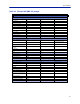
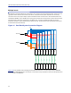
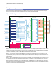
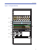
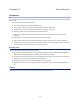
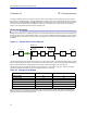
Table Of Contents

FiberDistributedAntennaSystem(FiberDAS)
41
Chapter 6 RF Commissioning
Inordertomaketheprocessmoreclearforthispartofthemanualwewillconsidersettingupafictitioussystem,
butbasedonastandardapproachatdoingFiber‐DAS.Thesystemthatweareconsideringwillhavetwofrequency
bands,let’sassumeGSM900MHzandUMTS2100MHz
.Theexamplewillhave2sectorswithtworemotesineach
sector.Ofcourseyoursystemmaylookdifferent,bemoreorlesscomplexbutinordertomakeitclearhowthe
systemissetupthisshouldprovideyouwithastartingpoint.
Setting up the uplink
SettinguptheuplinkmeanstoadjustthesystemforanoptimalworkingpointfromtheantennaportoftheRemote
UnittotheactualinputontheRadioBaseStation.Thiscanbedoneindifferentwaysdependingonhowthesystem
isdesigned.Wewillherediscussastandardset‐upst
artingwithasmallblockschematicshowinghowthesystemis
connected.
Figure 19
System Interconnect Diagram
Themainparameterthatwewillbediscussingisthe”netgain”ofthesystem.Thismeansthetotalchangeinsignal
fromtheRemoteUnitantennaporttothereceiverportonthebasestation.Therearedifferentwaysofsettingthis
systemupbutwewilllookata0dBne
tgainsystemwhichisagoodstartingpointformostsystems.
Thesy
stemgaincanbecalculatedasthegainintheRemoteUnit–Lossonfiber+FOIgain–POIloss+BIUgain–
couplerloss.Basicallythistakesformofalinkbudgetandhereisanexample:
Table 45
Unit/Component Gain/Loss (dB) Accumulated Gain/Loss (dB)
RemoteUn
it(RU)
Fiber‐Op
ticCable
FOI
POI
BIU
Coupler
Example Link Budget
BasicallythismeansthatwhateverisinputattheantennawillalsobeseenatthesamelevelfortheRadioBase
Stationreceiver.Thisisnotabadstartingpointbutdoesnottakeintoaccountthenoiseloadonthebasestation
whichwillincreasesomewhatwiththissetup
40 40
-10 30
20 50
-35 15
015
-15 0