
User Manual
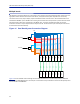
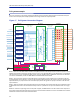
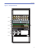

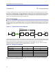
Table Of Contents

FiberDistributedAntennaSystem(FiberDAS)
35
Full system example
HereisanexampleofafullsystemshowingtheMasterUnitandthefibersthatgoesofftotheRemoteUnits(not
showninthisexample)withmultipleoperatorsandalargenumberoffrequencybands.
Figure 17
! !
!
!
!
!
!
!
!
" "
"
"
"
"
"
#
$
"
"
%&
'(
%
%
'(
%&
'(
%
%
'(
'(
%
%
'(
%&
#$$)
'(
%
%
'(
%&
#$$)
'(
%
%
'(
%&
$$)
'(
%
%
'(
%&
$$)
!
'(
%
%
'(
%&
$$)
"
'(
%
%
'(
%&
$$)
*(+%,-+
./0
*(+%,-+
/0.0
' '
/01
' '
* *
* *
* *
* *
'%
(
0
0
'%
(
0
'%
'%
'%
'%
'%
'%
'%
'%
'%
'%
'%
'%
'%
'%
(
(
(
(
(
(
(
(
(
(
(
(
(
(
0
0
0
0
0
0
0
0
0
0
0
0
0
0
2%3
4+5+1%3%
6 7
8%9&8
6
/ /
Full System Connection Diagram
Block1:Hereareall theBaseStationInterfaceUnits(BIU)cardsforallthefrequencybandsandtheoperators.Inthis
exampletwooperatorsmayshareoneBIU.Thefirstunit1:1isforFMradiowhichisonlyDownlinkasitisbroadcast.
Thesecondunit1:2isforasaf
etybluelightserviceusingtheTETRAsystemon400MHz.ThentherearetwoBIU’s
1:3and1:4forGSM900,similarforGSM1800andforUMTS2100andLTE2600.
Block2:ThisisthePo
intofInterconnect(POI)whereallthesignalsfromtheoperatorsarecombinedonthefour
couplingfieldsofthefirstPOI(2:1).TherearetwoULfieldsandtwoDLfields.Thecommonportsarethenfedintoa
hybridcombiner(2:3,2:4)andontothesec
ondPOI(2:2)wherethesignalsaresplituptoconnecttoalltheFiber‐
opticInterfaces.
Block3:The
searethefiber‐opticinterfaces(FOI)andinthisexampleupto16FOIcardsmaybeconnectedforatotal
of16RemoteUnitsifthereareoneRemoteUnitperfi ber.ItispossibletouseuptofourRemoteUnitsonasingle
fiber.
Block4‐6:The
searesupportingunitssuchaspowersupplies,theBGWwhichisthealarmandcontrolcomputerin
thesystemandtheEthernetSwitchthatconnectsthecommunicationbetweenallunitsintheMasterUnitandalso
handlesthecommunicationswiththeRemoteUnits.