
User Manual
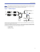
Table Of Contents

SystemDescription
12
Figure7
isablockdiagramshowingthedownlinkpathintheFOIandhowthetestportisconnected.Asyoucan
seether
earetwoattenuatorsthatcanbesetintheDLpath,thisallowsforbalancingtheinputsignalsfromtwo
differentsignalsourcessothattheycansharethedynamicsofthelaserproperly.
Figure 7
FOI Block Diagram
TheRFdrivelevelsaremeasuredandaccessibleinthewebinterfacesothattheycanbechecked.Inthefuture
alarmlevelsmaybeaddedtothesetestpoints.
Thisin
terfaceisdesignedtoworkwithSC‐APCconnectors(7°angledphysicalconnector)andsinglemodefibers
only.Allconnectorsbetweenthemasterunitandtheremoteunitshouldbeofangledtype,otherwiseproblems
withreflectionswillarisewhichmaycausesevereproblemsinthesystem.
Sing
lemodefiber
Angledconnectors
Opticalloss<15dB