
User Manual
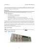
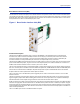
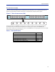
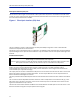
Table Of Contents

FiberDistributedAntennaSystem(FiberDAS)
11
Fiber Optic Interface (FOI) unit
TheFOIcon vertstheRFsignalsinthedownlinktofiber ‐opticallaseroutputthatistransmittedonthefi bertothe
remoteunit.ItalsoreceivesthelaserlighttransmittedbytheRemoteUnitandconvertsitbacktoRFsignalsthatare
thenroutedtothePOIand thentotheBIU
.
Figure 6 Fiber Optic Interface (FOI) Unit
TheFOIisavailableineitherasingleheadfiberinterface(withWDM)configurationorwithadualheadfiber
interfacewithseparateRXandTXconnectors.
EachFO
Icanserveupto4RemoteUnitsonasinglefiber.ThedrawbackisthattheRemoteUnitsmusthavedifferent
opticalwa velengthsintheuplinktoavoidinterference.Theycanhoweversharethesameopticalwavelengthinthe
downlink.
Functional description
TheFO
Ihasanominalgainof35dBandthelasertransmittershouldseeamaximumcompositeinputpowerofca
0dBm.Thismeansthatfor0dBattenuationintheDLamaximuminputof‐35dBmcomposit epoweris
recommended(whenattenuatorsaresetto0dBm).IftheDLatte
nuatorissettoahighervaluethemaximum
recommendedinputisadjustedaccordingly.
Theoutputpo
werofthelaseriscalibratedto3000µW.Thiscanbeusedtocheckthelossoverfiberintheremote
becausetheremotereportsthereceivedopticallevels.ThelossmaybedifferentintheULcomparedtotheDL
becauseofdifferentwavelengthsonthela
ser.
TheFO
IispoweredfromtheMFUbackplaneandcommunicateswithEthernetwiththeothermodulesintheMaster
Unit.
Theun
itcontainsseveraladjustableattenuatorswhichareusedtocompensateforlossbeforetheFOI(e.g.inthe
POI)andforlossonthefiberintheuplink.TherearetwosetsofRFportsontheFOIthatcanbeusedtoconnect
signalsfromtwodifferentstripsinthePOI.
TheEt
hernetcommunicationbetweentheMasterUnitandtheRemoteUnittake splaceontwosub‐carriersinthe
FOIwheretheEthernetsignalsaresuperimposedontheRFsignals.
WARNING
Avo
idlookingintoconnectedfi bersandreceptacles.
ThelaserusedinthissystemisaClass3blaserthatproducesinvisibleinfra‐redcoherentlight.Notsafetoview
withopticalinstruments.Alwaysputtheprotectioncapsonunusedfibersandreceptacles.