
User Manual
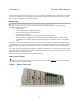
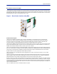
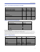
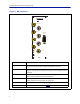
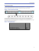
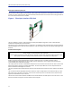
Table Of Contents

SystemDescription
8
Table 3 RF and electrical performance of the BIU
Parameter Value Unit
Downlinkatte
nuation Settable 10‐30±3 dB
UplinkGa
informodules<1000MHz Settable 10to20±3 dB
UplinkGa
informodules>1000MHz Settable ‐10to10±3 dB
IM3perf
ormance >55 dB
Maxinp
utnon‐destructive >36 dBm
Highinp
utalarmthresholdlevel 33 dBm
Lowin
putalarmthresholdlevel 10 dBm
Inputre
turnloss >20 dB
Impedancefo
rallRFports 50 Ω
Isolationbe
tweenports >60 dB
Powercon
sumption <15 W
Temperaturera
nge 0‐45 °C
Table 4 BIU mechanical specifications
Parameter Value
Basest
ationRFports SMA,Female
Testportsup
link(ifpresent) SMA,Female
InterconnectingRFpo
rtstoPOI QMA,Female
Alarmc
onnector DB9,Female
Dimensions,RackUn
it
Width 2U
Height 3U
BIU Indicator Operation
TheBIUha
stwoLEDslocatedonthefrontpanel.OneisthepoweronLED(green)andtheotheristhealarmLED
(red).BothLEDsindicateanumberofstatesbydifferentflashingbehaviors.
Inanerr
orstatethewebinterfaceshouldbeusedtochecktheactualconditionoftheBIUbuttheLEDsonthefront
cangiveyouaquickindicationonthestateoftheunit.Itisalsousefulforlocatingthephysicalunitifyouhave
severalBIUsinstalledinthesamera
ck.
Table 5
State ON LED ALARM LED Note
Booting 2Hz Off Normalboot
Bootings
tandalonemode 2Hz 2Hz Notattachedtorack
BootingreadofMA
Caddressfailed 2Hz On Error
Starting 0,1Hz90
% 0,1Hz90% Kernelstartup
Operation 0,5Hz10
% Off Normaloperation
Operation 0,5Hz10
% 1Hz10% Minoralarmstate
Operation 0,5Hz10
% 2Hz25% Majoralarmstate
Operation 0,5Hz10
% On Criticalalarmstate
Indicator behavior