
User Manual
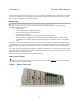
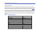
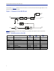
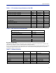
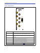
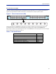
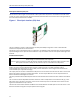
Table Of Contents

FiberDistributedAntennaSystem(FiberDAS)
7
Theschematicin
Figure3
showstheblocksintheBIUforoneofthechannelsandhowthesignaldetectorforthe
downlinkle
velalarmsareconnected.
Figure 3 Schematic of One BIU RF path
Table2
listsstandardcellularBIU’s.Otherconfigurationsareavailableuponrequestaswellasunitswithout
internaldu
plexfi ltering.
Table 2 Standard variants of the BIU
Part No Configuration
UL
MH
z
DL
MHz
BTS
I/F
DBI303
2xTETRA39
0MHz
†
†. Severaloptionsexistsfor5MHzstandardbandsforTETRA
380‐38
5 390‐395 Duplex
DBI307 2x70
0MHZABC‐band 698‐716 728‐746 Duplex
DBI308S 2xSM
R800 806‐825 851‐870 Duplex
DBI308 2x850MHz 824‐84
9 869‐894 Duplex
DBI309 2x90
0MHz 880‐915 925‐960 Duplex
DBI318 2x18
00MHz 1710‐1785 1805‐1880 Duplex
DBI319 2x19
00MHz 1850‐1910 1930‐1990 Duplex
DBI320 2xUMT
S2100MHz 1920‐1980 2110‐2170 Duplex
DBI321 2xAW
S2100MHz 1710‐1755 2110‐2155 Duplex