
User's Manual Part 2


RFCommissioning
110
Noise load on Radio Base Station
Thesystemwillinevitablyaddsomenoisetothereceiver.Whenproperlysetupthenoisefigureinasystemlikethis
willbebetterthan3dB.However,ifthegainisimproperlysetup(i.e.notenoughgainintheremote,toomuchgain
inthehead‐end)itispossibletocr
eateaverybadnoisefigure.InordertoavoidthistheFiber‐DASCalculatorshould
beusedtocalculatethenoisefigureofthesystemintheuplink.
Ifyouhaveno
tfamiliarizedyourselfwiththeFiber‐DASCalculator,dosobeforemovingoninthismanual.The
figuresintheFiber‐DAScalculatorrelatetothesettingsofallstepsinthechain.Byusingthecalculator,youcan
determinethepropersettingsonceyouknowthefiberlossbe
tweentheRemoteUnitandtheheadend.
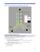
Letusassumeyo
urhavearrivedataNoiseFigure(NF)of3dBforthischain.Howeveryoursystemmaycontain
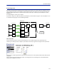
moreremotes,perhapsconnectedlikethesystemin
Figure134
.
Figure 134
!
Multiple RU Connection Diagram
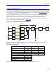
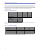
Nowthenoiseloadcanbecalculatedbyaddingthenoisecontributionfromeachstepofthechain.Belowisan
exampleofnoisefiguresfromeachoftheremotes:
Table 69
Chain NF Gain Noise Load
RU1
RU2
RU3
RU4
BaseStati
on
Fib
er‐DASNo
iseLoad
TotalNoisein
toBTS
Noise Load
AddyourfigurestothesheetintheFiber‐DAScalculatoranditwillcalculateitforyou.
2.8 0.0 2.8
3.2 1.0 4.2
3.8 -2.0 1.8
2.6 -1.0 1.6
Sum of Noise Load 8.7
4.0
8.0
9.5
Desensitization -5.5