
User's Manual Part 2


109
Chapter 6 RF Commissioning
Inordertomaketheprocessmoreclearforthispartofthemanualwewillconsidersettingupafictitioussystem,
butbasedonastandardapproachatdoingFiber‐DAS.Thesystemthatweareconsideringwillhavetwofrequency
bands,let’sassumeGSM900MHzandUMTS2100MHz.The
examplewillhave2sectorswithtworemotesineach
sector.Ofcourseyoursystemmaylookdifferent,bemoreorlesscomplexbutinordertomakeitclearhowthe
systemissetupthisshouldprovideyouwithastartingpoint.
Setting up the uplink
SettinguptheuplinkmeanstoadjustthesystemforanoptimalworkingpointfromtheantennaportoftheRemote
UnittotheactualinputontheRadioBaseStation.Thiscanbedoneindifferentwaysdependingonhowthesystem
isdesigned.Wewillherediscussastandardset‐upstartingwithasma
llblockschematicshowinghowthesystemis
connected.
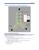
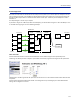
Figure 133
System Interconnect Diagram
Themainparameterthatwewillbediscussingisthe”netgain”ofthesystem.Thismeansthetotalchangeinsignal
fromtheRemoteUnitantennaporttothereceiverportonthebasestation.Therearedifferentwaysofsettingthis
systemupbutwewilllookata0dBnetga
insystemwhich isagoodstartingpointformostsystems.
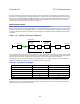
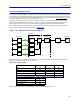
Thesystemga
incanbecalculatedasthegainintheRemoteUnit–Lossonfiber+FOIgain–ICUloss+BIUgain–
couplerloss.Basicallythistake sformofalinkbudgetandhereisanexample:
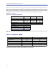
Table 68
Unit/Component Gain/Loss (dB) Accumulated Gain/Loss (dB)
RemoteUnit(RU)
Fib
er‐OpticCable
FO
I
ICU
BIU
Coupler
Example Link Budget
BasicallythismeansthatwhateverisinputattheantennawillalsobeseenatthesamelevelfortheRadioBase
Stationreceiver.Thisisnotabadstartingpointbutdoesnottakeintoaccountthenoiseloadonthebasestation
whichwillincreasesomewhatwiththissetup.
40 40
-10 30
20 50
-35 15
015
-15 0