
User's Manual
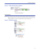
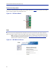
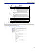
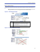
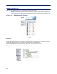
Table Of Contents
- Safety Precautions
- About This Manual
- Table of Contents
- Chapter 1 Introduction
- Chapter 2 System Description
- Chapter 3 Installation guidelines
- Chapter 4 DAS Software Configuration
- Chapter 5 Commissioning
- Chapter 6 RF Commissioning
- Chapter 7 Model Identification

FiberDistributedAntennaSystem(FiberDAS)
87
FOR Opto Gain and Attenuation Settings
Figure 98
1
2
FOR Opto Gain Settings
Asettingof+20indicatesnoattenuationsoFORwillhave+20dBgain(+20dBgainminus0dB
attenuation).
Asettingof+1
0willhave10ofattenuationsothisstagewillhave10dBmofgain(+20dBgainminus
10dBofattenuation).
Asettingof0
willhave20dBofattenuationsothisstagewillhaveunitygain(+20dBgainminus
20dBofattenuation).
Ase
ttingof‐10wi
llhave30dBofattenuationsothisstagewillhave10dBofloss(+20dBgainminus
30dBofattenuation).
Asettingof‐20
willhave40dBofattenuationsothisstagewillha ve20dBofloss(+20dBgainminus
40dBofattenuation).
Aset
tingof+20
willhavefullgainof+20dBm.
Asettingof+1
0willhave+10dBgain.
Asettingof0
willhavenogain.
Factoryde
faultshouldbeusedunlesshighlossinfiber.NotethatchangesinGainuplinkwill
requirechangesintheFORULALClevel.
Item Description
1
FORga
ininthedownlinkpa th.Rangeistypicallyfrom‐20to+20.FORdownlinkpathhasinhere nt/rawgainof
+20dB(FMto2600MHz).
2
FOR
gainintheuplinkpath.Rangeistypicallyfrom0to+20dBm(FMto2600MHz).