Ametrine Heavy Hinge Shower Door 5/16" glass (8mm) Ametrine Con Bisagras Resistentes Puerta de Ducha Vidrio de 5/16” (8 mm) INSTALLATION GUIDE / GUÍA DE INSTALACIÓN CAUTION: To reduce the risk of breakage, keep corner protectors on glass while installing. PRECAUCIÓN: Durante la instalación, coloque vidrio o protectores de esquinas para reducir el riesgo de romperse. Keep corner protectors for use in case future adjustments are needed.
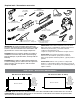
Required tools / Herramientas necesarias Stud Finder Detector de montantes 1/8" Drill Bit Broca de 1/8" 1/4" Drill Bit Broca de 1/4" Closed-Toe Shoes Zapatos cerrados 32 TPI 32 TPI 7/32" Tile Drill Bit Broca para azulejos de 7/32" 3" Deep Miter Box Caja de ingletes de 3" de profundidad 3' Level or longer Nivel de 3' o más largo Metal File Lima para metales 100% Silicone Sealant – Clear Sellador de silicona 100 % - Transparente Cut Resistant Non-Slip Gloves Guantes antirresbalantes y resistentes al
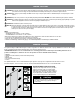
BEFORE YOU START CAUTION: R isk of injury or product damage. During installation tempered glass should not come in direct contact with metal parts or hard surfaces (such as tile/concrete flooring) or it may shatter. Gaskets and bushings must always be used between glass and metal. CAUTION: Risk of injury or product damage. DO NOT touch the edges of tempered glass with tools. DO NOT attempt to cut tempered glass or it will shatter.
ANTES DE COMENZAR PRECAUCIÓN: Riesgo de lesión o daño del producto. Durante la instalación, el vidrio templado no debe entrar en contacto directo con piezas metálicas ni superficies duras (como el piso de hormigón) o puede romperse. Entre el vidrio y el metal siempre deben utilizarse juntas y bujes. PRECAUCIÓN: Riesgo de lesión o daño del producto. No toque los bordes del vidrio templado con las herramientas. No intente cortar el vidrio templado o se romperá.
CARTON PARTS IDENTIFICATION / IDENTIFICACIÓN DE LAS PARTES See following pages for detailed component diagrams / Consulte en las páginas siguientes los diagramas detallados de los componentes Pieza A B Descripción Panel de puerta con bisagras Panel fijo 2 1 1 4 1 2 C AA BB CC DD EE Conjunto de bisagras Cuerpo de bisagra Placa trasera de bisagra Junta de bisagra Buje recortado de bisagra Tornillo hexagonal de bisagra - M6x14 2 1 1 4 1 2 Wall Side Hinge Door Seal Fixed Panel Strike Seal Fixed Panel
DOOR ASSEMBLY / MONTAJE DE LA PUERTA CAUTION: To reduce the risk of breakage, which may result in personal injury, property damage or product failure, DO NOT set glass panels on a hard surface or on their edge. G PRECAUCIÓN: Para reducir el riesgo de rotura, que puede provocar lesiones, dañ os a la propiedad o fallas del producto, NO coloque los paneles sobre una superficie dura ni sobre su borde.
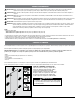
HARDWARE / ERRAJE EE x2 BB CC x4 C x2 Hinge Assembly Conjunto de bisagras DD S x2 G AA Support Bar Barra de apoyo Hex Screw M4 x12 Tornillo hexagonal M4x12 GG Q HH T T FF Z Z XX YY FF M Set Screw M4x3 Tornillo prisionero M4x3 N Hex Screw M4x20 Tornillo hexagonal M4x20 II Padded Glass Screw M5 Tornillo recubierto para vidrio–M5 L W W L N M Dam Support–Left Apoyo de barrera, izquierda Dam Support–Right Apoyo de barrera, derecho 7
HARDWARE / ERRAJE JJ NN H x2 Fixed Panel Wall Bracket Soporte de pared del panel fijo MM x3 S R U KK OO Z LL RR x2 S NN PP W QQ I Fixed Panel Sill Bracket Soporte fijo para el alféizar del panel Allen Wrenches Included Llaves Allen Incluidas R x10 Wall Screw Cap Tapa de tornillo de pared S x7 Hex Screw Cap Tapa de tornillo hexagonal T x2 Dam Strip Support Cap Tapa de apoyo de barrera EE U x1 Sill Bracket Cap Tapa de soporte de umbral ZZ Spare Water Diverter Desviador de agua de repuesto
HARDWARE / ERRAJE TT VV UU SS WW O Handle Mango 9
CAUTION: To avoid personal injury or property damage, identify components and read all instructions before installing. RECAUCIÓN: Para evitar lesiones o daños a la propiedad, identifique los componentes y lea todas las instrucciones antes de P la instalación. IMPORTANT: Incorrect measurement may prevent proper door closure. Double-check measurement. Before beginning installation, verify the door assembly will fit within the horizontal opening of the shower enclosure.
3 This Ametrine Heavy Hinge Shower Door can be installed to open from either side of your enclosure. Determine which side of your enclosure you would like to install your hinged door and fixed panel. The Fixed Panel must be secured by a stay bar which will extend into the shower. NOTE: For the purposes of these instructions, the installation will be shown with the Hinged Door Panel (A) to the Left of the enclosure.
Door Panel Orientation The door panel should be oriented with the “This Side In” label facing the inside of the enclosure and the notches for the hinges toward the wall. This will ensure that the Spot Guard Coating of the door panel is oriented towards the inside of the shower. 5 Orientación del panel de la puerta El panel de la puerta debe orientarse con la etiqueta “This Side In” (Esta cara hacia adentro) hacia el interior del recinto y las muescas para las bisagras hacia la pared.
7 Keeping the hinged door panel (A) in a secure horizontal position, install hinge body (AA), gaskets (CC), cutout bushing (DD) and back hinge plates (BB) to the hinge door panel with allen wrench provided. Ensure that two gaskets (CC) are placed on each side of the glass under the metal plates of the hinge. Hand tighten until secure. Repeat for the remaining hinge.
9 Carefully, and with assistance, position the hinged door panel (A) into place against the side wall supported by blocks (P). Ensure that Glass Notice label is facing into the shower and the decorative side of the hinges are facing outside. Cuidadosamente, y con ayuda, apoyado en los bloques (P) posicione el panel de puerta con bisagras (A) en el lugar correcto contra la pared lateral.
11 Using a pencil, mark location of all four screw holes for both hinge assemblies (C). Usando un lápiz, marque la ubicación de los cuatro orificios de los tornillos para ambos conjuntos de bisagras (C). de pue ar s o dri te stal one s, l vi es in si le : E tira de ar le eria s vo ar IA C re te it at si al N se an ev s m he inst TE si vo ara o ad e ER se si . P dañ to s d V er D p he es y au ué A m ad el les te p ro to pan na es des au s so re a .
13 Drill a 1/8" pilot hole at each location marked for both hinges (C). Next, redrill a 1/4" hole at each location to accept the 8mm bracket anchor (V). En cada ubicación marcada perfore un orificio guía de 1/8" para ambas bisagras (C). Después, vuelva a perforar un agujero de 1/4" en cada ubicación para que acepte el anclaje de soporte de 8 mm (V). CAUTION To avoid risk of injury or product damage, make sure that you drill into studs.
Carefully, and with assistance, reposition the hinged door panel (A) into the installation location on top of the provided installation support blocks (P) for vertical support. Ensure that the “This Side In” label is facing into the shower and the decorative side of the hinges face the outside of the shower.
Leveling Step Ensure that edge of glass door (A) is vertical. If needed, hinge shims (Q) can be installed behind hinges to adjust for an out-of-plumb condition. A Paso de nivelación Asegúrese de que el borde de la puerta de vidrio (A) esté vertical. De ser necesario, pueden instalarse plaquitas de bisagras detrás de estas para ajustarlas en caso de desviación. Q 17 Fixed Panel (B) Orientation Either side of Fixed Panel (B) may face into the shower area.
18 The provided base U-channel gasket (J) is sized to be the correct length for the Fixed Panel of the 60" System Assembly. If installing a 60" enclosure (B), skip to step 21. If installing a 48" enclosure (B), proceed to next step. ure s o cl el En Pan " 60 xed Fi B La junta del canal en U de base (J) suministrada se dimensiona para que tenga la longitud correcta para el panel fijo del Conjunto del Sistema de 60” (B). Si se instala un recinto de 60” (B), vaya al paso 21.
Remove corner protectors from the corners of Fixed Panel (B) that will be against the wall. Locate the fixed panel bubble seal (F). Install bubble seal (F) along the wall edge of fixed panel (B). This will be the side with holes as shown in figure 20. 2 Retire los protectores de esquina de las esquinas del Panel Fijo (B) que están contra la pared. Coloque la junta de burbuja de panel fijo (F). Instale la junta de burbuja (F) a lo largo del borde de la pared del Panel Fijo (B).
22 Install Fixed Panel Wall Brackets (H) to Fixed Panel Using the provided Allen wrench, disassemble wall bracket (JJ), gaskets (MM), bushing (LL) and front plate (KK) by removing the bracket hex screws (NN). JJ Instalando los soportes de pared del panel fijo (H) en el panel fijo Con la llave Allen incluida, desarme el soporte de pared (JJ), las juntas (MM), el buje (LL), y la placa frontal (KK) removiendo los tornillos hexagonales del soporte (NN).
Installing the Fixed Panel (B) Carefully, and with assistance, position fixed panel (B) into place. Use caution when gently placing glass panel onto sill area. Ensure that U-Channel rests evenly on sill. 24 Instalando el Panel Fijo (B) Cuidadosamente, y con ayuda, coloque el panel fijo (B) en el lugar correcto. Tenga cuidado al colocar suavemente el panel de vidrio sobre el área del umbral. Asegúrese de que el canal en U descanse uniformemente sobre el umbral.
26 Using a pencil or masking tape, mark the bottom edge of the fixed panel (B) on the sill near the hole for the Fixed Panel Sill Bracket (I). This line will be used to mark the position of the fixed panel on the sill. Con un lápiz o cinta de enmascarar, marque el borde inferior del panel fijo (B) en el umbral cerca del agujero para el Soporte de Umbral del Panel Fijo (I). Esta línea se utilizará para marcar la posición del panel fijo en el umbral.
CAUTION To avoid risk of injury or product damage, make sure that you drill into studs. 28 Carefully set fixed panel aside on a soft surface. Next, drill a 1/8" pilot hole at each location. PRECAUCIÓN Re-drill a 1/4" hole at each location for bracket anchor 8mm Para(V). evitar el riesgo de lesiones o daños al producto, asegúrese de perforar en los montantes. Cuidadosamente coloque el panel fijo a un lado sobre una superficie suave. Luego, perfore un orificio guía de 1/8" en cada ubicación.
Carefully, and with assistance, reposition fixed panel (B) in place to fasten the fixed panel wall brackets (H) to side wall. Use caution when gently placing glass panel onto sill area. Ensure that U-channel rests evenly and is on sill. 30 Cuidadosamente, y con ayuda, reposicione el panel fijo (B) en su lugar para sujetar los soportes de pared del panel fijo (H) a la pared lateral. Tenga cuidado al colocar suavemente el panel de vidrio sobre el área del umbral.
32 Attaching the Fixed Panel Sill Bracket (I) to Fixed Panel and Sill Using provided hex wrench, disassemble Fixed Panel Sill Bracket (I) as shown in figure 33. RR Fijando el Soporte de Umbral del Panel Fijo (I) al Panel Fijo y al Umbral. Utilizando la llave hexagonal suministrada, desarme el Soporte de Umbral del Panel Fijo (I) como se muestra en la figura 33.
34 *Inside Enclosure* *Dentro del recinto* If Fixed Panel (B) has shifted during installation, reposition bottom edge of the fixed panel (B) into alignment with location marked in step 26. Position the sill bracket back plate (OO) on the inside of the door and using a pencil, mark the location of the sill support hole. Double check the alignment with hinged door panel (A) before proceeding. Distance between vertical edges of Door Panel and Fixed Panel should be even top to bottom.
36 *Inside Enclosure* *Dentro del recinto* Insert 6 mm support anchor (W) into hole. The anchor should fit securely into drilled hole. If needed, a rubber mallet can be used to insert the anchor. To reduce risk of property damage, metal hammers are not recommended to be used. If hole is too tight to insert the anchor, use drill to slightly enlarge the opening of the hole. NOTE: Anchor MUST be used. For ceramic tile, use the included tile sill anchors.
38 *Inside Enclosure* *Dentro del recinto* Secure the fixed panel sill bracket (I) to the sill using the sill support screw (Z). Hand tighten to fully secure. Asegure el soporte de umbral del panel fijo (I) al umbral usando el tornillo de apoyo del umbral (Z). Ajuste A MANO hasta que quede completamente firme. Z 39 1 E Identify fixed panel strike seal (E). Remove the last corner protector on the fixed panel (B), and install the Fixed Panel Strike Seal (E) as shown in figure 39.
40 Installing Support Bar Using provided Allen wrenches, carefully loosen set screws on the support bar (G) for adjustment. Instalando la barra de apoyo Usando las llaves Allen incluidas, cuidadosamente afloje los tornillos prisioneros en la barra de apoyo (G) para el ajuste. G 41 GG Use stud finder to locate stud for determining position of the support bar (G). Adjust location so that the back support ring (GG) is aligned with a stud. Use a pencil to mark the location of the back support ring.
42 6-2 0c Support bar (G) should be positioned between 2-3/8" (6 cm) and 7-7/8" (20 cm) from outer edge of fixed panel as shown in figure 42. NOTE: Support bar (G) should assist in alignment between strike seal (E) and hinged door panel (A). m La barra de apoyo (G) debe colocarse entre 2-3/8" (6 cm) y 7-7/8" (20 cm) desde el borde exterior del panel fijo como se muestra en la figura 42.
44 Use alignment marks on wall made in step 41 to position the support ring (GG) and mark hole locations using a pencil. Use las marcas de alineación en la pared hechas en el paso 41 para posicionar el apoyo circular (GG) y marque las ubicaciones de los orificios usando un lápiz. GG CAUTION To avoid risk of injury or product damage, make sure that you drill into studs. PRECAUCIÓN Para evitar el riesgo de lesiones o daños al producto, asegúrese de perforar en los montantes.
46 W Insert 6 mm support anchor (W) in each hole location. The anchors should fit securely into drilled holes. If needed, a rubber mallet can be used to insert anchors. To reduce risk of property damage, metal hammers are not recommended to be used. If needed, use drill to slightly enlarge the opening of the hole. NOTE: Wall anchors MUST be used. For ceramic tile, use the included tile wall anchors. Inserte un anclaje de apoyo de 6 mm (W) en cada ubicación de orificio.
48 Replace support ring cover (HH) on the support ring (GG). Insert the main rod fixture (FF) and fasten with set screw. ? Vuelva a colocar la cubierta del apoyo circular (HH) en el apoyo circular (GG). Inserte el accesorio de varilla principal (FF) y fíjelo con el tornillo prisionero. GG 2 1 HH FF 3 49 Insert glass gasket (II) in fixed panel end of support bar (G). Inserte la junta para vidrio (II) en el extremo del panel fijo de la barra de apoyo (G).
50 Position support bar (G) on fixed panel. Tighten all set screws on top of support bar (G) to secure position. 1 Coloque la barra de apoyo (G) en el panel fijo. Ajuste todos los tornillos prisioneros en la parte superior de la barra de apoyo (G) para asegurar su posición. 2 51 Hand tighten Padded Glass Screw on inside of enclosure using a flat head screwdriver to fully secure.
52 XX 2 1 Installing Dam Strip (L) Position the Dam Strip Support - Right (M) and Dam Strip Support - Left (N) on the left and right edges of the Hinge Door Panel (A). Insert Fixed Panel Trim Unit (XX) into the Dam support on the Fixed Panel (B) side. This side will vary depending on which side of the enclosure the fixed panel is installed. Use the Hinge Side Trim Block (YY) to fill the open space in the Dam Strip Support - Left (N) next to the wall.
54 B Using a measuring tape, measure distance between the inner edges of the brackets. Add 0.75" to this measurement. This will be Measurement “B”, the length of the bottom track. The additional distance allows the Dam Strip Supports (M and N) to overhang the dam strip. Width of opening + 0.75" _ = ________ f measurement “B” + .7 5” = Usando una cinta métrica, mida la distancia entre los bordes internos de los soportes. Agregue 0,75" a esta medición.
56 IMPORTANT: Double check the measurement before cutting. Using a miter box, cut the Dam Strip (L) with a finetoothed (32 TPI) hack saw. If needed, use a metal file to smooth rough edges. Clean metal shavings. CAUTION IMPORTANT: NOT standdamage, on or use vicethat to hold To avoid risk ofDO injury or product makeasure Dam while youStrip drill into studs.cutting. L IMPORTANTE: Vuelva a comprobar la medición antes de cortar.
58 Insert 6 mm support anchor (W) into each hole. The anchors should fit securely into the holes. If needed, a rubber mallet can be used to insert anchors. To reduce risk of property damage, metal hammers are not recommended to be used. If needed, use drill to slightly enlarge the opening of the hole. NOTE: Anchors MUST be used. For ceramic tile, use the included tile sill anchors. W Inserte el anclaje de apoyo de 6 mm (W) en cada orificio. Los anclajes deben encajar firmemente dentro de los orificios.
60 Apply a thick bead of silicone on underside of Dam Strip (L) as shown in figure 60. Aplique un cordón denso de silicona en la parte inferior de la Barrera (L) como se muestra en la figura 60. L 61 Slide the dam strip (L) into the Dam Strip Support (M) against fixed panel and position under door. Deslice la barrera (L) en el Apoyo de Barrera (M) contra el panel fijo y colóquela debajo de la puerta.
62 YY Fasten the remaining Dam Strip Support against the enclosure wall under the hinges using Sill Support Screw (Z). Ensure the Hinge Side Trim Block (YY) is inserted to fill the open space in the dam strip support (N). Secure with silicone. Hand tighten Sill Support Screw (Z) to fully secure. N Fije el Apoyo de Barrera restante contra la pared del recinto debajo de las bisagras usando el Tornillo de Apoyo del Umbral (Z).
64 Using a pencil, or other marking tool (such as masking tape), mark distance "C" from the previous step along Bottom Door Seal (K). Use Tin Snips to cut Bottom Door Seal (K) to length. Con un lápiz u otra herramienta de marcado (como cinta de enmascarar), marque la distancia "C" del paso anterior a lo largo de la Junta Inferior de la Puerta (K). Use Tijeras para Chapa Fina para cortar la Junta Inferior de la Puerta (K) a la longitud correspondiente.
66 Identify Wall Side Hinge Door Seal (D). This component will need to be cut into 3 segments to install. Measure the distance between, above, and below the hinges along the glass panel as shown in figure 66. Transfer measurements to Wall Side Hinge Door Seal (D) and cut Seal segments to length using tin snips. Identifique la Junta de Puerta de Bisagra del Lado de la Pared (D). Este componente se debe cortar en 3 segmentos para instalarlo.
68 Attaching Door Handle Disassemble handle body (SS), gaskets (UU) and bushings (TT) by removing upper knob (VV) and lower handle plate (WW). UU 2 VV Fijando el mango de la puerta Desarme el cuerpo del mango (SS), las juntas (UU) y los bujes (TT) retirando el botón superior (VV) y la placa inferior del mango (WW).
70 Use silicone caulk to seal the outside edge of the bottom track under the door and the inside edge of the fixed panel. Ensure that all connection points between bottom track and dam strip supports (M and N) are fully sealed. Follow manufacturer’s recommendation for curing time on silicone. A Utilice masilla de silicona para sellar el borde exterior del carril inferior debajo de la puerta y el borde interior del panel fijo.
72 Install Wall Screw Caps (R) on the wall screws (X). Install Hex Screw Caps (S) on the glass panel hex screws (NN). Caps should hold in place with a press fit. If needed, silicone can be used to secure. R Instale Tapas de Tornillo de Pared (R) en los tornillos de pared (X). Instale Tapas de Tornillo Hexagonal (S) en los tornillos hexagonales del panel de vidrio (NN). Las tapas deben mantenerse en su lugar por ajuste a presión. De ser necesario, puede usarse silicona para asegurarlas.
Optional Install the water diverter (ZZ) Shower environments can have different types of shower head fixtures and orientations. If needed for additional water retention, an additional water diverter (ZZ) has been provided and can be cut and installed if needed as shown. E Opcional Instalando el desviador de agua (ZZ) Los ambientes de ducha pueden tener diferentes tipos y orientaciones de accesorios de cabezales de ducha.
TROUBLESHOOTING Symptom: Alignment Recommended Action 1. Hinged Door Panel does not align with Strike Seal Adjust location of Support Bar (G) against glass to align. See Steps 42 and 50. 2. The bottom track is cut too short. Add sealant as needed to ensure watertight seal. See steps 61, 62 and 70. If additional sealant is insufficient, please call Delta Customer Service at 1-800-964-4850. 3. Top of Hinge Door Panel does not align with top of Fixed Glass Panel. See Leveling Step (top of page 18).
SOLUCIÓN DE PROBLEMAS Síntoma: Alineación Síntoma: Alineación 1. El Panel de Puerta con Bisagras no se alinea con la Junta de Contacto Ajuste la ubicación de la Barra de Apoyo (G) contra el vidrio para alinearla. Consulte los pasos 42 y 50. 2. El carril inferior se corta demasiado corto. Agregue el sellador necesario para garantizar un sello hermético. Consulte los pasos 61, 62 y 70. En caso que el sellador adicional no lo solucione, llame al Servicio al consumidor de Delta al 1-800-964-4850. 3.