
User's Manual


UMAC Turbo CPU/Communications Board Hardware Manual
Introduction 3
Option 5F0 provides a 240 MHz DSP56321 CPU w/192Kx24 internal memory, 128Kx24 SRAM
compiled/ assembled program memory, 128Kx24 SRAM user data memory, and 1Mx8 flash
memory. Requires V1.940 or newer firmware.
Option 5F3 provides a 240MHz DSP56321 CPU w/192Kx24 internal memory, expanded 512Kx24
SRAM compiled/assembled program memory, expanded 512Kx24 SRAM user data memory, and
4Mx8 flash memory. Requires V1.940 or newer firmware.
Option 8: High-Accuracy Clock Crystal
The UMAC Turbo CPU/Communications Board has a clock crystal of nominal frequency 19.6608 MHz
(~20 MHz). The standard crystal’s accuracy specification is ±100 ppm.
Option 8A provides a nominal 19.6608 MHz crystal with a ±15 ppm accuracy specification.
Option 10: Firmware Version Specification
Normally, the UMAC Turbo CPU/Communications Board is provided with the newest released firmware
version. A label on the flash memory IC shows the firmware version loaded at the factory.
Option 10 provides for a user-specified firmware version.
Option 16A: Battery-Backed Parameter Memory
The contents of the standard memory are not retained through a power-down or reset unless they have been
saved to flash memory first. Option 16A provides supplemental battery-backed RAM for real-time
parameter storage that is ideal for holding machine state parameters in case of an unexpected power-down.
Option 16A provides a 32k x 24 bank of battery-backed parameter RAM.
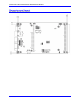
Connectors and Indicators
J7 – Main Serial Port (RS-232 Port)
J7 is the primary serial communications port. For serial communications, use a serial cable to connect the
PC’s COM port to the board’s serial port connector. Delta Tau provides the Acc-3L cable to connect the
UMAC Turbo CPU/Communications Board to a DB 9 connector.
J8 – Auxiliary Serial Port (RS-232 Port)
J8 is the auxiliary serial communications port. For serial communications, use a serial cable to connect
the PC’s COM port to the board’s serial port connector. Delta Tau provides the Acc-3L cable to connect
UMAC Turbo CPU/Communications Board to a DB 9 connector.
J9 – USB Port
This connector is used in conjunction with USB A-B cable which can be purchased from any local
computer store, and is provided when Option 1A is ordered. The A connector is connected to a PC or
Hub device; the B connector plugs into the J9-USB port.
J10 – Ethernet Port
This connector is used for Ethernet communications from the UMAC Turbo CPU/Communications Board
to a PC.
TB1 – Watchdog Relay
In case of watchdog failure, the contacts of a relay present on this connector will change state.
LED Indicators
When lit, the D1 Red LED indicates a watchdog failure.
When lit, the D2 Green LED indicates that the 5V power supply is applied to the board.
When lit, the D8 Green LED indicates that a USB or Ethernet cable is plugged in and ready to
establish communications.