
User's Manual


UMAC Turbo CPU/Communications Board Hardware Manual
Board Jumpers 11
BOARD JUMPERS
E0: Factory Use Only
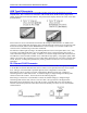
E1: Write Enable Protect for USB/Ethernet Communication Firmware
E Point and
Physical Layout
Description
Default
Remove jumper for normal operation. User cannot change IP or
upload communication firmware in this mode.
Jump pins 1 to 2 to enable IP change and uploading USB/Ethernet
communication firmware.
No jumper installed
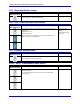
E1A: Servo and Phase Clock Direction Control
E Point and
Physical Layout
Description
Default
Jump pins 1 and 2 to use its internally generated servo and phase
clock signals and to output these signals on the J7 serial port
connector. E1B should connect pins 2 and 3.
Jump pins 2 and 3 for the UMAC Turbo system to expect to
receive its servo and phase clock signals on the J7 serial port
connector. E1B should also connect pins 1 and 2.
See also jumpers E17A, E17B, E18A, and E18B
Pins 1-2 jumpered
E1B: Servo/Phase Clock Source Control
E Point and
Physical Layout
Description
Default
Jump pin 1 to 2 to get phase and servo clocks from J7 serial port
connector (from an external source such as another PMAC).
Jump pin 2 to 3 to get phase and servo clocks from P1 backplane
connector (from an Acc-24E2x, or equivalent board).
Pins 2-3 jumpered
E2: Reserved for Future Use
E3: Re-Initialization on Reset Control
E Point and
Physical Layout
Description
Default
Remove jumper for normal reset mode (default).
Jump pins 1 to 2 for re-initialization on reset.
No jumper installed
E4: Reserved for Future Use