
User's Manual


UMAC Turbo CPU/Communications Board Hardware Manual
Connections 9
CONNECTIONS
Backplane (UMAC) Connections
To connect the UMAC Turbo CPU/Communications Board to the UBUS backplane, simply insert the P1
connector into one of the sockets on an Acc-Ux UBUS backplane board. It does not matter which socket
on the UBUS backplane board is used, although customarily, the CPU board is installed in the leftmost
slot. Typically, the backplane board will have been installed already in a Eurorack frame (Acc-Px or
equivalent), so the CPU board is simply slid into one of the slot guides in the frame until it mates with the
backplane board; then the front-plate screws are tightened for a firm connection to the rack and
backplane.
If a power supply has been connected to the UBUS backplane board, this power will be supplied
automatically to the Turbo CPU board. The UBUS backplane board is capable of supplying isolated
analog and digital supplies, but the 3U-format power supplies (Acc-Ex) provided by Delta Tau do not
keep these two supplies isolated from each other.
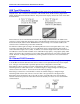
PC/104 Connections
If the PC/104 connector is installed, the UMAC Turbo CPU/Communications Board may be mounted on
the top of a PC/104 stack. Because it does not pass the connector through, it may be mounted only on the
top of such a stack. The UMAC Turbo CPU/Communications Board has four mounting holes in the
standard PC/104 locations for standoff connections to the PC/104 stack. Note that the PC/104 connector
used on the UMAC Turbo CPU/Communications Board provides for the Eurocard 4T standard of 20 mm
(0.8”) spacing between boards, not the PC/104 standard of 15mm (0.6”), so standoff lengths must be
chosen accordingly.
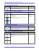
Serial Port Connections
The standard J7 serial-port connector on the front edge of the UMAC Turbo CPU/Communications Board
is an IDC 10-pin header. The connector is designed so that a standard flat-cable connection (such as a
Delta Tau Acc-3L cable) to a DB-9 connector can be used. From there, a standard DB25-to-DB9 adapter
can be used if necessary. The servo and phase clock signals can be either input or output on this
connector, depending on the setting of jumpers E1A, E1B, E17A, E17B, E18A and E18B.
The auxiliary J8 serial-port connector is also an IDC 10-pin header. The connector is designed so that a
standard flat-cable connection (such as a Delta Tau Acc-3L cable) to a DB-9 connector can be used.
From there, a standard DB9-to-DB25 adapter can be used, if necessary.