
User's Manual


UMAC Turbo CPU/Communications Board Hardware Manual
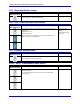
Jumpers Setup Summary 8
Reference Voltage Connect Jumper
Jumper E12 permits the reference voltage for the analog and digital circuits in the UMAC Turbo
CPU/Communications Board to be tied together. If not isolating the analog circuits from the digital
circuits, this jumper should be ON. If isolating the analog circuits from the digital circuits using separate
isolated supplies for the two circuits, this jumper should be OFF.
Interrupt Select Jumpers
If the PC/104-bus interface is installed, the UMAC Turbo CPU/Communications Board can interrupt the
PC/104 host computer over one of four interrupt lines as selected by jumpers E7 – E10. One of these
jumpers should be ON in any configuration.
E7 ON selects interrupt line IRQ10
E8 ON selects interrupt line IRQ11
E9 ON selects interrupt line IRQ12
E10 ON selects interrupt line IRQ15
Flash Memory Bank Select Jumpers
The flash-memory IC has the capacity for eight separate banks of firmware, only one of which can be
used at any given time. The eight combinations of settings for jumpers E25A, E25B, and E25C select
which bank of the flash memory is used. In the factory production process, firmware is loaded only into
Bank 0, which is selected by having all of these jumpers OFF.
PC/104 Bus Use Selection
If the PC/104 bus communications method is used, jumper E5 must be installed in position 1-2. If the
USB or Ethernet communications ports are used, jumper E5 must be installed in position 2-3.
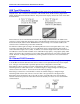
USB/Ethernet Firmware Reload Jumpers
Jumper E1 should be OFF to engage the “Write Protect” feature. This is the default factory shipped
setting. To load new firmware into the USB/Ethernet micro-controller jumper E1 must be installed to
disable “Write Protect”.
Jumper E6 should be ON for normal operation. Jumper E6 should only be removed when directed by a
Delta Tau Technical Support Engineer to reset the USB/Ethernet processor. To do so jumper E6 should
be removed (OFF) before the card is powered; this puts the on-board USB/Ethernet micro-controller in
bootstrap mode. After power-on the jumper must be replaced (ON) to allow writing to the micro-
controller to accept new firmware (as well as setting ON the E1 jumper).
Note:
The jumper E1 may be left in the ON position but this will disable the “Write
Protect” feature.