
User's Manual


UMAC Turbo CPU/Communications Board Hardware Manual
Jumpers Setup Summary 7
JUMPER SETUP SUMMARY
On the UMAC Turbo CPU/Communications Board, there are many jumpers (pairs of metal prongs),
called E-points. Some have been shorted together; others have been left open. These jumpers customize
the hardware features of the board for a given application and must be set up appropriately. The
following is an overview of the several UMAC Turbo CPU/Communications Board jumpers.
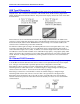
Clock Source Jumpers
In order to operate, the board must receive servo and phase clock signals from a source external to the
board. These clock signals can be brought into the board from one of two possible ports: the UBUS
backplane connector, or the front-side main serial-port connector. Jumpers E1A and E1B must be
configured properly for the clock source used.
To receive the clock signals over the UBUS backplane, usually from an Acc-24E2x axis-interface board
or an Acc-5E MACRO-interface board, E1A must connect pins 1 and 2, and E1B must connect pins 2 and
3. Use this default setup in most cases.
To receive the clock signals through the main serial port, usually from another PMAC system or a
reference signal generator, E1A must connect pins 2 and 3 and E1B must connect pins 1 and 2. Though
rarely used, this configuration permits complete synchronization to the system that is generating the clock
signals.
To either input or output the clock signals through the J7 serial port, jumpers E17A, E17B, E18A, and
E18B must be configured in positions 2-3. Otherwise, these jumpers must be set at position 1-2.
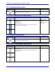
Watchdog Timer Jumper
Jumper E19 should be OFF for normal operation, leaving the watchdog timer circuit active and prepared
to shut down the card in case of a severe problem. Putting jumper E19 ON disables the watchdog timer
circuit. This should be used for test purposes only to try to track down the source of watchdog timer trips.
Normal operation of a system with this jumper ON should never be attempted, as an important safety
feature is disabled.
Operation Mode Jumpers
Jumpers E20, E21, and E22 control the operational mode of the UMAC Turbo CPU/Communications
Board. For normal operation, E20 must be OFF, E21 must be ON, and E22 must be ON. Other settings
of these jumpers are for factory use only.
Firmware Reload Jumper
Jumper E23 should be OFF for normal operation. To load new firmware into the flash-memory IC on the
CPU, E23 should be ON when the card is powered up. This puts the card in bootstrap mode, and ready to
accept a new firmware. Then try to establish communications to the card with the Executive program, the
Executive program will recognize that the card is in bootstrap mode automatically, and prompt for the
firmware file to download.
Re-Initialization Jumper
If jumper E3 is installed when the board is powered-up or reset, the board firmware will go through a re-
initialization process, returning most I-variables to factory default values. The last saved values are not
lost when this happens. It will also go through a system auto-detection process, selecting which of the
Servo ICs that it finds will be the source of the servo and phase clock signals for the system. Typically,
this jumper is used only when the system’s setup has a problem severe enough that communications does
not work – otherwise, a $$$*** command can be used for re-initialization.