^1 HARDWARE REFERENCE MANUAL UMAC Turbo CPU/Communications Board ^3 HRM for UMAC Turbo CPU/Communications Board ^4 3xx-603766-xHxx ^5 April 26, 2012 Single Source Machine Control Power // Flexibility // Ease of Use 21314 Lassen Street Chatsworth, CA 91311 // Tel. (818) 998-2095 Fax. (818) 998-7807 // www.deltatau.
Copyright Information © 2009 Delta Tau Data Systems, Inc. All rights reserved. This document is furnished for the customers of Delta Tau Data Systems, Inc. Other uses are unauthorized without written permission of Delta Tau Data Systems, Inc. Information contained in this manual may be updated from time-to-time due to product improvements, etc., and may not conform in every respect to former issues. To report errors or inconsistencies, call or email: Delta Tau Data Systems, Inc.
REVISION UPDATE REV. 1 2 3 4 5 6 7 8 DESCRIPTION Added CE declaration of conformity USB/Ethernet Description, P.14, 19, 23 Watchdog Terminal Block Info Corrections to J8 Table, P.17 Added UL Approval Logo on manual cover Updated Agency Approval &Safety Section E12 default jumper settings should be "no jumper installed" Added Jumper E1 Clarified E1 and E6 jumper description DATE CHG 08/24/06 CP 05/07/07 CP 10/12/07 CP 06/13/08 CP APPVD S. Fierro S. Milici S. Milici S.Sattari 09/29/09 CP S.
TABLE OF CONTENTS Copyright Information ............................................................................................................................................ ii Operating Conditions.............................................................................................................................................. ii INTRODUCTION ................................................................................................................................................
E12: Digital/Analog Reference Connect ............................................................................................................... 13 E17 – E18: Serial Port Servo and Phase Clocks Enable ........................................................................................ 13 E19: Watchdog Disable Jumper ........................................................................................................................... 14 E20 – E22: Power-Up/Reset Load Source ....................
OPTION 16: BATTERY BACKED MEMORY ................................................................................................ 40 Safety and Handling of Lithium Batteries ............................................................................................................. 40 DECLARATION OF CONFORMITY .............................................................................................................. 42 APPENDIX ............................................................................
UMAC Turbo CPU/Communications Board Hardware Manual INTRODUCTION The UMAC (Universal Motion and Automation Controller) is a modular system built with a set of 3Uformat Eurocards. The configuration of any UMAC system starts with the selection of the UMAC Turbo CPU/Communications Board and continues with the addition of the necessary axes boards, I/O boards, and any other interface boards selected from a variety of available accessories.
UMAC Turbo CPU/Communications Board Hardware Manual Board Configuration Base Version The base version of the UMAC Turbo CPU/Communications Board without options provides a single board 160 mm wide and 100 mm high for a 20 mm slot with: 80 MHz DSP56303 CPU (120 MHz PMAC equivalent) (fast internal memory for first 15 axes servo and commutation) 128k x 24 SRAM compiled/assembled program memory (5C0) (for firmware, compiled PLCs, userwritten servo and phase) 128k x 24 SRAM user data memory (5C0) (for mot
UMAC Turbo CPU/Communications Board Hardware Manual Option 5F0 provides a 240 MHz DSP56321 CPU w/192Kx24 internal memory, 128Kx24 SRAM compiled/ assembled program memory, 128Kx24 SRAM user data memory, and 1Mx8 flash memory. Requires V1.940 or newer firmware. Option 5F3 provides a 240MHz DSP56321 CPU w/192Kx24 internal memory, expanded 512Kx24 SRAM compiled/assembled program memory, expanded 512Kx24 SRAM user data memory, and 4Mx8 flash memory. Requires V1.940 or newer firmware.
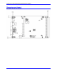
UMAC Turbo CPU/Communications Board Hardware Manual Dimensions and Layout Part Number 603766-103 and newer Introduction 4
UMAC Turbo CPU/Communications Board Hardware Manual SPECIFICATIONS Environmental Specifications Description Specification Operating Temperature Storage Temperature Humidity 0°C to 45°C, -25°C to 70°C 10% to 95 % non-condensing Notes Physical Specifications Description Specification Dimensions w/o PC/104 Option Length: 16.256 cm (6.4 in.) Notes Height: 10 cm (3.94 in.) Dimensions with PC/104 Option Width: 3.05 cm (1.2 in.) Length: 16.256 cm (6.4 in.) Height: 10 cm (3.94 in.) Weight Width: 2.
UMAC Turbo CPU/Communications Board Hardware Manual Electrical Specifications Description Specification Power Requirements 5V @ 1.0A (10%) Option 16 Battery Size: PC Type: Lithium Voltage: 3.6V Rated Capacity: 1.0 Ah Notes ElectroChem QTC85 series lithium battery part number 3B880.
UMAC Turbo CPU/Communications Board Hardware Manual JUMPER SETUP SUMMARY On the UMAC Turbo CPU/Communications Board, there are many jumpers (pairs of metal prongs), called E-points. Some have been shorted together; others have been left open. These jumpers customize the hardware features of the board for a given application and must be set up appropriately. The following is an overview of the several UMAC Turbo CPU/Communications Board jumpers.
UMAC Turbo CPU/Communications Board Hardware Manual Reference Voltage Connect Jumper Jumper E12 permits the reference voltage for the analog and digital circuits in the UMAC Turbo CPU/Communications Board to be tied together. If not isolating the analog circuits from the digital circuits, this jumper should be ON. If isolating the analog circuits from the digital circuits using separate isolated supplies for the two circuits, this jumper should be OFF.
UMAC Turbo CPU/Communications Board Hardware Manual CONNECTIONS Backplane (UMAC) Connections To connect the UMAC Turbo CPU/Communications Board to the UBUS backplane, simply insert the P1 connector into one of the sockets on an Acc-Ux UBUS backplane board. It does not matter which socket on the UBUS backplane board is used, although customarily, the CPU board is installed in the leftmost slot.
UMAC Turbo CPU/Communications Board Hardware Manual USB Type B Receptacle This connector is used in conjunction with USB A-B cable which can be purchased from any local computer store. The A connector is connected to a PC or Hub device; the B connector plugs into the UMAC Turbo CPU/Communications Board. The picture below displays what the two ends on the cable should look like. This connector is used to communicate with the host PC through a USB connection.
UMAC Turbo CPU/Communications Board Hardware Manual BOARD JUMPERS E0: Factory Use Only E1: Write Enable Protect for USB/Ethernet Communication Firmware E Point and Physical Layout Description Remove jumper for normal operation. User cannot change IP or upload communication firmware in this mode. Jump pins 1 to 2 to enable IP change and uploading USB/Ethernet communication firmware.
UMAC Turbo CPU/Communications Board Hardware Manual E5: Port Select E Point and Physical Layout Description Jump pin 1 to 2 to use the PC/104 bus communications. Jump pin 2 to 3 to use USB or Ethernet communication ports.
UMAC Turbo CPU/Communications Board Hardware Manual E6: USB/Ethernet Micro-Controller Reset Enable E Point and Physical Layout Description Remove jumper to reset USB/Ethernet Micro-Controller on powerup\reset – replace after power-on. Install jumper for normal operations. Default Pins 1-2 jumpered E7 – E10: IRQ PC Interrupt Select E Point and Physical Layout Description E7: Jump E7 pin 1 to 2 to permit UMAC to interrupt PC on PC/104 bus interrupt line IRQ10.
UMAC Turbo CPU/Communications Board Hardware Manual E19: Watchdog Disable Jumper E Point and Physical Layout Description Jump pin 1 to 2 to disable Watchdog timer (for test purposes only). Remove jumper to enable Watchdog timer. Default No jumper installed E20 – E22: Power-Up/Reset Load Source E Point & Physical Layout E20: E21: Description To load active memory from flash IC on power-up/reset/remove jumper E20; Jump E21 pin 1 to 2 Jump E22 pin 1 to 2.
UMAC Turbo CPU/Communications Board Hardware Manual DIP Switch Block S1: PC Bus Base Address S1B S1A 4 3 2 1 8 7 6 5 4 3 2 1 OFF OFF OFF OFF OFF OFF OFF OFF OFF OFF OFF OFF ON ON ON ON ON ON ON ON ON ON ON ON The 12 DIP switches on block S1 set the base address of the UMAC Turbo CPU/Communications Board on the PC/104 bus. Together they form a binary number.
UMAC Turbo CPU/Communications Board Hardware Manual CONNECTOR SUMMARY J1A, B: J2C, D: J5: J6: J7: J8: J9: J10: J21: P1: TB1: PC/104 Main Connector, 64-pin prong connector PC/104 AT Connector, 40-pin prong connector JTAG/OnCE (for factory use only) 10-pin IDC connector JISP (for factory use only): 8-pin SIP connector RS-232/RS-422 Serial Port Connector Auxiliary RS-232 Serial Port USB Port Ethernet Port JISP_B (for factory use only) (SIP 8 connector) UBUS Expansion Port (96-pin DIN connector) Watchdog indi
UMAC Turbo CPU/Communications Board Hardware Manual Connector Summary 17
UMAC Turbo CPU/Communications Board Hardware Manual BOARD CONNECTOR PINOUTS J7: Primary Serial Port Connector (RS232) Front View Pin # Symbol Function Description Notes 1 PHASE+ In/Out Phasing Clock 2 DTR \ PHASEBidirect Data Terminal Ready 3 TXD/ Input Receive Data Low True 4 CTS Input Clear to Send High True 5 RXD/ Output Send Data Low True 6 RTS Output Request to Send High True 7 DSR \ SERVOBidirect Data Set Ready 8 SERVO+ In/Out Servo Clock 9 GND Common Board Common 10 +5V Output +5VDC Supply See
UMAC Turbo CPU/Communications Board Hardware Manual J10: Ethernet Port Pin # Function 1 2 3 4 5 6 7 8 9 10 TXD+ TXDRXD+ No Connect No Connect RXDNo Connect No Connect No Connect No Connect This connector is used for Ethernet communications from the UMAC to a PC. The appropriate Category 5 10/100-Base T network cable that mates to this connector can be purchased from any local computer store. The type of network cable to purchase depends on the configuration to the host PC.
UMAC Turbo CPU/Communications Board Hardware Manual ETHERNET SOFTWARE SETUP Note: Note that for proper USB/Ethernet communication the host address as set by the 12 position switch, SW1, must be set to the default of 528 (210h). IP Setup Using the Ethernet port requires Pewin Pro with at least Service Pack 2.0. Earlier revisions of software are not capable of communicating with the Ethernet port. Ethernet devices are configured by launching the Eth2Configure.
UMAC Turbo CPU/Communications Board Hardware Manual By default, the address 192.6.94.5 should appear in the Store IP edit box. If it does not, enter it there. To alter the address from the default, enter a unique IP in the Store IP edit box. Click the Store IP button.
UMAC Turbo CPU/Communications Board Hardware Manual Windows OS TCP/IP Setup Ethernet mode of communication is supported by dedicated network only. A network card must be configured on the computer to which the UMAC Turbo CPU/Communications Board connection is used before completing the following steps. Further, a crossover Ethernet cable or a private hub along with two straight cables is required for this setup. (See the RJ45 section of Hardware Setup.) 1.
UMAC Turbo CPU/Communications Board Hardware Manual Determining if TCP/IP is Setup Correctly To determine if the TCP settings on the CPU board and the PC are compatible from a Windows command prompt, type Ping IP address where IP address is the IP address of the UMAC card (i.e., 192.6.94.5).
UMAC Turbo CPU/Communications Board Hardware Manual USB SOFTWARE SETUP Device Driver Installation Note: Note that for proper USB/Ethernet communication the host address as set by the 12 position switch, SW1, must be set to the default of 528 (210h). Starting with Pewin Pro and Service Pack 2.0, the USB driver support for this revision of the card is bundled with the Pewin Pro installation program. The UMAC USB card will work only with Windows 98, Windows ME, Windows 2000 and Windows XP.
UMAC Turbo CPU/Communications Board Hardware Manual If Delta Tau UMAC USB 2.0 Device is not on the list, the device driver has not been installed. If there is a red x through that line or a yellow exclamation point through that line, then Windows had a problem installing the device. The appropriate trouble-shooting steps are: 1. Reboot the computer and examine this list again. 2. If that does not work, ensure that pmacusb.sys is in the Windows\system32\Drivers directory. 3.
UMAC Turbo CPU/Communications Board Hardware Manual PEWIN PRO SOFTWARE SETUP First Time User (Register the Newly Installed Devices) 1. Once the driver is installed, it needs additional configuration by using the PmacSelect dialog. The PmacSelect dialog is accessible by all programs created with PComm 32 Pro (via the PmacSelect() function call). Launch the supplied Delta Tau application (Pewin 32 Pro, PMAC Test Pro, or any application) from the program menu and display the PmacSelect dialog.
UMAC Turbo CPU/Communications Board Hardware Manual Pewin Pro Software Setup 27
UMAC Turbo CPU/Communications Board Hardware Manual USING DPRAM If Option-2B is ordered, the UMAC Turbo CPU/Communications Board contains its own on-board DPRAM. This DPRAM can be used for automatic reporting features or as a general-purpose scratch pad area for custom data. DPRAM for General Purpose Scratch Pad Data The UMAC Turbo CPU/Communications Board can write to any DPRAM memory location. Use MVariables to point to an area in the $60000-$60FFF address range.
UMAC Turbo CPU/Communications Board Hardware Manual Now the DPRAM automatic real-time/background function can be enabled or disabled from the SelectDevice menu. Set the update period and motor mask. After turning on DPRAM automatic features, exit Pewin Pro and then restart it to activate the automatic features. After doing this, the speed of response when running the executive probably will slow down slightly since now the PC is reading the automatic data from DPRAM continually and placing it in PC memory.
UMAC Turbo CPU/Communications Board Hardware Manual UPGRADING COMMUNICATIONS FIRMWARE The UMAC Turbo CPU/Communications Board can have its communications firmware upgraded via its USB port. This is useful for getting the latest firmware to take advantage of bug fixes and new features. Upgrading Ethernet or USB Firmware Caution: Do not stop the firmware upgrade in the middle of its loading. Do not load application firmware into the boot loader. Do not load boot loader firmware in the application firmware.
UMAC Turbo CPU/Communications Board Hardware Manual The DPRAM offset is the number of bytes from the base DPRAM location. To compute this value, take the UMAC Turbo CPU/Communications Board DPRAM address and multiply its offset by 4. The offset is always the last three digits of the DPRAM address. For example, for the address $60D60 multiply $D60 by 4 to compute the offset; the offset for UMAC Turbo CPU/Communications Board address $60D60 is 0x3580.
UMAC Turbo CPU/Communications Board Hardware Manual ETHERNET PROTOCOL This section is intended for application programmers who have a fundamental understanding of Berkley sockets used in the TCP/IP protocol suite. Before any attempt to read or understand the contents of this manual, review basic sockets (recv, send and socket) and understand them before proceeding. The examples in this manual are for demonstration purposes only and to convey the concepts of how to communicate to the Delta Tau card.
UMAC Turbo CPU/Communications Board Hardware Manual #define #define #define #define VR_PMAC_WRITEBUFFER VR_PMAC_WRITEERROR VR_FWDOWNLOAD VR_IPADDRESS 0xC6 0xC7 0xCB 0xE0 wValue is request specific and its use is indicated under the description of each command. wLength indicates the length of the bData field below. bData is the meaningful data that is sent to the UMAC Turbo CPU/Communications Board.
UMAC Turbo CPU/Communications Board Hardware Manual EthCmd.RequestType = VR_DOWNLOAD; EthCmd.Request = VR_PMAC_SENDLINE; EthCmd.wValue = 0; EthCmd.wIndex = 0; EthCmd.wLength = htons( (WORD)strlen(outstr)); strncpy((char *)&EthCmd.bData[0], outstr ,(WORD)strlen(outstr)); Example: int CALLBACK PmacSockSendLine(char *outstr) { EthCmd.RequestType = VR_DOWNLOAD; EthCmd.Request = VR_PMAC_SENDLINE; EthCmd.wValue = 0; EthCmd.wIndex = 0; EthCmd.wLength = htons( (WORD)strlen(outstr)); strncpy((char *)&EthCmd.
UMAC Turbo CPU/Communications Board Hardware Manual VR_PMAC_GETBUFFER This packet causes the Ethernet connection to return any available string that may be residing in the PMAC. All characters up to an or are returned. If a or character is detected, only the data up to the next is returned. The maximum amount of data returned is 1400 Bytes.
UMAC Turbo CPU/Communications Board Hardware Manual VR_PMAC_PORT This packet sends or receives a single byte to or from the UMAC Turbo CPU/Communications Board. To send data to the host port, set the packet as follows. After sending the packet, the programmer must wait to receive one byte via the Recv function before continuing. The data received is irrelevant; its purpose is to ensure that the sender’s command was received. EthCmd.RequestType EthCmd.Request EthCmd.wValue EthCmd.wIndex EthCmd.
UMAC Turbo CPU/Communications Board Hardware Manual VR_PMAC_WRITEBUFFER This packet writes multiple lines to the PMAC with just one packet. Set up the packet as follows. The received data is the response to the sent control character. Usually, it is used for downloading a file. Data should have each line separated by null byte. For Example, OPEN PLC 1 CLEAR<00>P1=P1+1<00>CLOSE<00> where <00> indicates a null byte.
UMAC Turbo CPU/Communications Board Hardware Manual EthCmd.wIndex = 0; EthCmd.wLength = htons( (WORD)strlen(outstr)); strncpy((char *)&EthCmd.bData[0],outstr,(WORD)strlen(outstr)); send(sock,(char*)&EthCmd,ETHERNETCMDSIZE + strlen(outstr),0); recv(sock, szPmacData,1400,0); VR_PMAC_GETMEM This packet causes the Ethernet connection to retrieve DPRAM data from the UMAC Turbo CPU/Communications Board. Up to 1400 bytes may be received in a single packet.
UMAC Turbo CPU/Communications Board Hardware Manual memcpy(EthCmd.bData,&mask,len); // Send command request send(sock,(char *)&EthCmd,ETHERNETCMDSIZE+len,0); recv(sock,(char *)&errcode,1,0); VR_PMAC_SETBITS This packet causes the Ethernet connection to perform a write to the DPRAM shared between the PMAC and the PMAC that sets bits in a 32-bit word to a new value. The wValue field contains the byte offset to retrieve the data..
UMAC Turbo CPU/Communications Board Hardware Manual OPTION 16: BATTERY BACKED MEMORY The contents of the standard memory are not retained through a power-down or reset unless they have been saved to flash memory first. Option 16A provides supplemental battery-backed RAM for real-time parameter storage that is ideal for holding machine state parameters in case of an unexpected powerdown.
UMAC Turbo CPU/Communications Board Hardware Manual Please visit the ElectroChem website at www.electrochempower.com to obtain specifications and all procedures or to go directly to the safety guidelines try: http://www.electrochempower.com/Support/SafetyHandling/safetyGuide.pdf Delta Tau cannot be held responsible for any mishandling by customers.
UMAC Turbo CPU/Communications Board Hardware Manual DECLARATION OF CONFORMITY Application of Council Directive: 89/336/EEC, 72/23/EEC Manufacturers Name: Manufacturers Address: Delta Tau Data Systems, Inc. 21314 Lassen Street Chatsworth, CA 91311 USA We, Delta Tau Data Systems, Inc.
UMAC Turbo CPU/Communications Board Hardware Manual APPENDIX Previous revisions Board Dimensions and Layout — Part Number 603766-100 through -102 Note: Revision 101 of this board does not have jumper E11, but has jumper E6.