
User's Manual
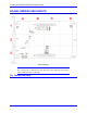
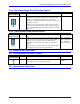
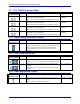

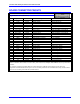
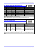
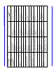
Table Of Contents
Turbo CPU Board for UMAC Turbo & Turbo Stack
20 Board Connector Pinouts
J8: Auxiliary Serial Port Connector (RS232)
(10-pin Header at Location A-3)
Front View
Pin # Symbol Function Description Notes
1 PHASE In/Out Phasing Clock
2 DTR Bidirect Data Terminal Ready Shorted to DSR.
3 TXD/ Input Receive Data Low TRUE
4 CTS Input Clear to Send High TRUE
5 RXD/ Output Send Data Low TRUE
6 RTS Output Request to Send High TRUE
7 DSR Bidirect Data Set Ready Shorted to DTR.
8 SERVO In/Out Servo Clock
9 GND Common Turbo PMAC2-3U Common
10 +5V Output +5VDC Supply
Note 1: If communicating to Turbo PMAC2-3U over this connector with a modem-style terminal emulator such as
Microsoft Windows Terminal, line 1 should not be connected.
Note 2: SERVO and PHASE are outputs if jumper E1 is OFF; they are inputs if Jumper E1 is ON.
The J8 connector provides an auxiliary RS-232 serial port, independent of the main serial port at J7. It is provided if
Option 9T is ordered.
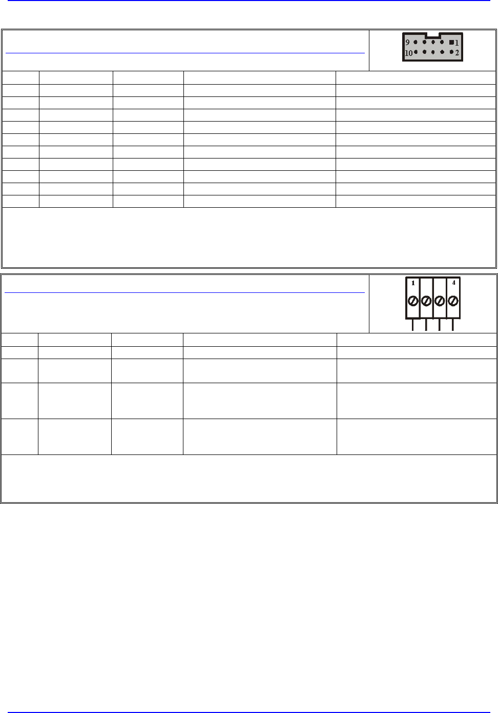
TB1: 4-Pin Terminal Block
(Location A-3)
Pin # Symbol Function Description Notes
1 GND Common Reference Voltage
2 +5V Input Positive Supply Voltage Supplies all Turbo PMAC2-3U
digital circuits
3 +12V Input Positive Supply Voltage +12V to +15V; Not required on-
board; used on J1 to supply analog
inputs
4 -12V Input Negative Supply Voltage -12V to +15V; Required for Opt-12
ADCs; used on J1 to supply analog
inputs
This terminal block can be used to provide the input for the power supply for the circuits on the Turbo PMAC2-3U
board when it is not in a bus configuration. When the Turbo PMAC2-3U is in a bus configuration, these supplies
automatically come through the bus connector from the bus power supply; in this case, this terminal block should not
be used.